
Technical Specifications
179
Truss & Rafter
© 2015 MiTek. All rights reserved.
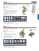
MUGT15 Girder Tiedown
Designed for higher uplift resistance for concrete block construction.
The MUGT15 can accommodate variable truss bearing depths.
Materials: 12 gauge
Finish: G90 galvanizing
Codes: See page 11 for Code Reference Chart
Installation:
• Use all specied fasteners. See Product Notes, page 17.
• When straps are wrapped over the truss, install nails in backside
of truss. See MUGT15 installation diagram for minimum nail
requirements into the face and on top of the truss.
• If installed straight-up with no wrap over the top of the truss,
ll all nail holes.
• Moisture barrier may be required.
Typical MUGT15
installation
MUGT15
Ref. No. Qty Dia. Top Face Back Type
160%
Face-Max 1 5/8 -- -- 28 -- -- 10d 4495
Top-Min 1 5/8 4 6 12 10d 4175
1) Allowable loads have been increased 60% for wind or seismic loads; no further increase shall be permitted.
2) Additional anchorage products to be designed by others.
3) Designer must specify anchor bolt type, length, and holdown device.
4)
NAILS:
10d nails are 0.148" dia. x 3" long.
New products or updated product information are designated in
blue font
.
Mounting
Condition
USP
Stock No.
Steel
Gauge
Qty
8, F4,
R10
MUGT15 MGT 12
DF/SP
Allowable Uplift
Loads (Lbs.)
1
Fastener Schedule
2,3,4
Anchor
Rafter/Truss
3
Code
Ref.
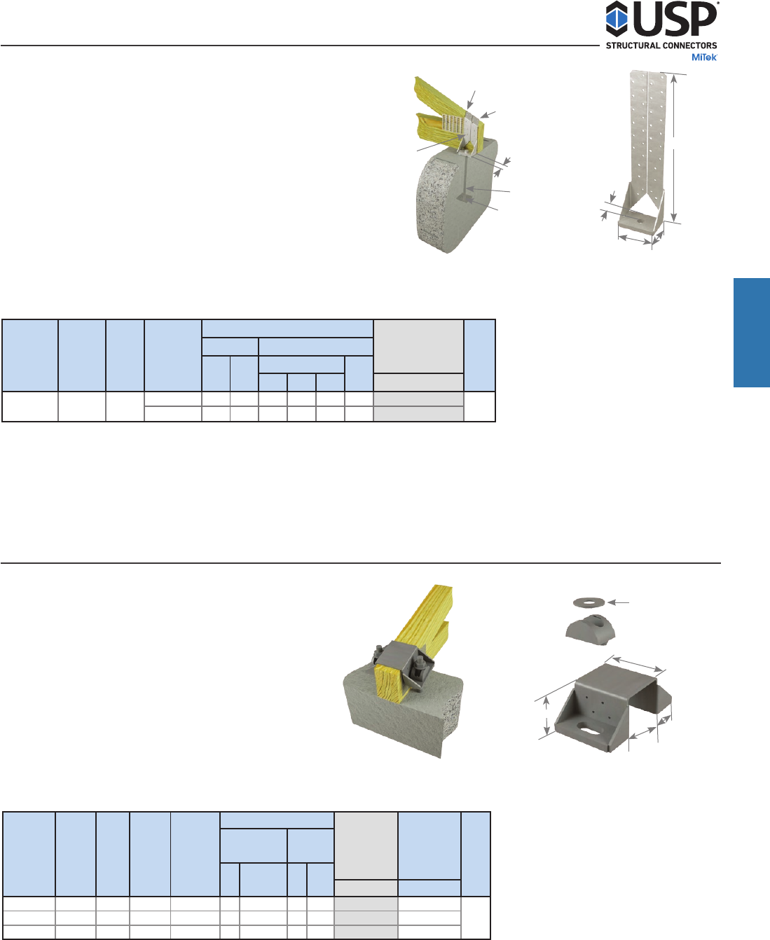
HUGT
Typical HUGT2
installation
The HUGT series high uplift girder tiedowns can be installed on
beams and top chords of trusses with slopes from 0˚ to 34˚.
Materials: 7 gauge
Finish: USP primer
Codes: See page 11 for Code Reference Chart
Installation:
• Use all specied fasteners. See Product Notes, page 17.
• Install the HUGT over the beam or truss (see “W” dimension
on chart for appropriate width).
• Attached members shall be designed to resist applied loads.
• Moisture barrier may be required.
Ref. No. Qty Qty Type
160% 160%
HUGT2 HGT-2 7 3-5/16 5-3/4 2 3/4 8 10d 9790 7020
HUGT3 HGT-3 7 4-15/16 7-3/8 2 3/4 8 10d 9860 9650
HUGT4 HGT-4 7 6-7/8 9 2 3/4 8 10d 9860 9860
1) Allowable loads have been increased 60% for wind or seismic loads; no further increase shall be permitted.
2) Listed loads apply where roof pitch is between 3:12 and 8:12.
3) Additional anchorage products to be designed by others.
4) Minimum nail penetration shall be 1-1/2" for 10d nails.
5) Designer must specify anchor bolt type, length, and embedment.
6)
NAILS:
10d nails are 0.148" dia. x 3" long.
USP
Stock No.
Steel
Gauge
Threaded
Rod
W
(in)
O.C. Dim
Between
Anchors
(in)
Fastener Schedule
3,6
Bolt
Dia.
Code
Ref.
F26
DF/SP
Allowable
Uplift Loads
(Lbs.)
1,2
S-P-F
Allowable
Uplift Loads
(Lbs.)
1,2
Girder
4
HUGT Girder Tiedowns
(2) 3/4" washers are
required if 3/4" dia.
bolt is used (washer
not included)
4"
2-3/16"
W
2-7/8"
Truss & Rafter
14-5/8"
1-1/4"
3-11/16"
2-7/16"
Install a minimum of (12)
10d nails into back
Install a minimum of (4)
10d nails into the top
5/8" bolt
1-1/4"
Min. 3" x 3" x 1/4"
bearing plate
Install a minimum of (6)
10d nails into face