
Technical Specifications

59
Holdowns
© 2015 MiTek. All rights reserved.
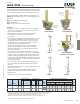
LSTAD / STAD Foundation Straps
The coined dimples below the embedment line allow for increased concrete
bonding. These holdowns retain high uplift capacity even when installed at
corners of foundation stemwalls. Ideal for use with built up 2x end posts.
RJ after the model indicates LSTAD or STAD for rim joist applications as in
STAD8RJ. Rim joist models provide for a 17" clear span without the loss of
strap nailing.
Materials: LSTAD-14 gauge; STAD-12 gauge
Finish: G90 galvanizing
Codes: See page 11 for Code Reference Key Chart
Installation:
• Use all specied fasteners. See Product Notes, page 17. The bottom
(2) nails are for form board attachment only and do not contribute to
fastener schedule requirements.
• Embed holdown in concrete to the embedment line (bend line).
• See illustrations for requirements on rebar, edge distances,
and clear spans.
• Bending the strap horizontally 90° to facilitate wall placement may cause
concrete behind the embedded strap to break away at the top edge
(spalling). If the spall is 1" or less from the top edge of the concrete,
no load reduction is necessary. If the spall is between 1" and 4" the
allowable load is 0.90 of the published chart load.
• When installing on lumber less than 3-1/2" wide, wood splitting
may occur. To reduce splitting, use 10d x 1-1/2" nails or ll every
other hole with 16d common nails. Reduce allowable loads per code
requirements accordingly.
• These straps do not secure concrete sections together at cold joints;
take other measures to transfer the load. If there is a cold joint between
slab and foundation, the minimum embedment must be made into the
foundation. Fastening opportunities may be reduced because the slab
pour level may be higher than some nail holes. Using fewer fasteners will
reduce allowable loads. Reduce allowable load by the code capacity for
each fastener not installed.
• To achieve full table loads the minimum center-to-center spacing is
twice the embedment depth (IE) when resisting tension loads at the
same time.
• Where fewer fasteners are used in the structural wood member, reduce
loads according to the code.
• There may be an increase in the amount of deection if the strap
is installed on the outside of the sheathing, versus directly to the
framing members.
• Strap may be bent one complete cycle to aid installation.
Typical STAD10
edge installation
Typical STAD10
corner installation
LSTAD
STAD
STAD_RJ
Typical STAD14RJ
corner rim joist installation
Ref. No. Qty Nail W L
L
E
D CS 1/2" 1-1/2"
l
E
1/2" 1-1/2"
l
E
1/2" 1-1/2"
l
E
6
8
6
8
1) Wood thickness shall be no less than 2".
2) Allowable tension loads have been increased 60% for wind or seismic loads; no further increase shall be permitted.
3) Interpolate allowable loads for edge distances between those listed. Nail quantities may be reduced for less
than lE corner distance design loads- use the code allowable loads for fasteners in shear.
4) Where fewer fasteners are used in the structural wood member, reduce loads according to the code.
5)
NAILS:
16d sinkers are 0.148" dia. x 3-1/4" long. 10d common (0.148" dia. x 3" long) nails may be substituted with no load reduction.
New products or updated product information are designated in
blue font
.
18-1/8 2225 2225
Min.
Stemwall
(in)
32203220 2225 2225 322014 24 16d Sinker 3 5
Code
Ref.
2000 psi 2500 psi 3000 psi
130
2225 2225 3220 22252225 2225 3220 2225 3220
2225 2225
Dimensions (in)
Steel
Gauge
14
Fastener Schedule
1,5
3 21-5/8 8 5
35-1/8 8
4-5/8
USP
Stock No.
LSTAD8
LSTAD8RJ LSTHD8RJ
LSTHD8 24 16d Sinker
DF/SP Allowable Tension Loads (160%)
2,3,4
Edge Distance - Concrete
Continued on next page
2x embedment
length + 12" min.
rebar length
1/2" min
rebar length
Edge distance
1/2" min from
corner
Edge distance
1/2" min from
corner
30" min rebar
length
Install (1)
#4 rebar in
shear cone
12" min. rebar
length
Nailed portion
CS
L
L
L
CS
CS
CS
W
W
W
D
D
D
Holdowns
I
E
I
E
I
E