
Technical Specifications

195
Plated Truss
© 2015 MiTek. All rights reserved.
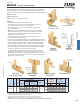
MSSHL/R Severely Skewed Hangers
USP’s MSSH217 hanger accommodates a skew range of 60° to 85° (30° maximum off
the girder) without the need for a more expensive custom design hanger. Face nail to
webs or bend the ange strap over the chord. Available in left (L) or right (R)congurations.
Materials: 18 gauge
Finish: G90 galvanizing
Codes: See page 11 for Code Reference Chart
Installation:
• Use all specied fasteners. See Product Notes, page 17.
• The 3 lower holes on each strap are for top nailing when the strap is bent
over the truss chord. These holes are not for face nailing.
• One or both straps may be bent over the bottom chord of the girder with
top or backside nailing.
• Note: Select the correct (right or left) hanger so that the strap on the outside
of the angle will pass the end of the truss. When facing the hanger, the strap
in the rear turns in the direction of the skew. The front strap turns to pass
behind the end of the carried member.
• Attach the hanger at the end of the truss with a single 10d (0.148" dia.) x
1-1⁄2" nail into the side ange or bottom.
• Place the truss in position against the girder. Push the outside strap past the end of the
truss to the girder web and face nail through the top 8 holes with 10d (0.148" dia.) x 1-1⁄2"
nails for a 1 ply girder, or 10d (0.148" dia. x 3") common nails for multiple-ply girders.
• The strap inside the angle can be formed over diagonal webs (if design allows) or
bend over the girder chord. Use two nails into the top and/or back side of the girder.
• If the outside strap does not contact a web, bend the strap tightly over the girder
chord. Use two nails into the top and/or back side of the girder.
• For uplift resistance, other means of attachment are required. If both the truss
and girder have vertical webs, attach a scab to pack out the girder web nearly
ush with the truss web and use a eld adjustable MP framing angle across the
two. A top chord connection for uplift requires a at LSTA strap tie wrapped under
the girder and over the truss chord.
MSSH217L
Left shown attached
to web and top of chord
MSSH217R
Right shown
attached to webs
Top view right shown
MSSH217R
right shown
Pocket Nail
8 holes for
face nailing
3 holes for
top nailing
2x6 or 2x8
Back side with
straps bent over
17-3/16"
1-5/8"
1-3/4"
Right shown
bent over bottom chord
Additional strapping
for high uplift
Additional strapping
for high uplift
Back view shown
Floor Floor
Qty Type Qty Type Qty Type 100% 115% 125% 100% 115% 125%
Face Mount -- -- -- -- 8 10d x 1-1/2 1470 1690 1700 1195 1205 1215
Top Mount 2 10d 4 10d x 1-1/2 1470 1690 1700 1265 1455 1580
Face Mount -- -- -- -- 8 10d 1700 1700 1700 1195 1205 1215
Top Mount 2 10d 4 10d 1700 1700 1700 1550 1630 1700
1) No uplift value with this hanger. Use other hardware or nailing higher on carried member to counteract uplift.
2) One or both straps may be bent over bottom chord of girder with top or backside nailing.
3) Maintain minimum 3/4" edge distance when installing nails.
4) The carried member shall be supported by blocking or other means to prevent rotation.
5)
NAILS:
10d x 1-1/2" nails are 0.148" dia. x 1-1/2" long, 10d nails are 0.148" dia. x 3" long.
Note: The 3 lower holes on each strap are for top nailing when strap is bent. These holes are not for face nailing.
MSSH217L/R -- --
Top
(per strap)
1 10d x 1-1/2
Ref.
No.
USP
Stock No.
Steel
Gauge
Mounting
Condition
Carried
Member
4
Carrying Member
Face/Backside
(per strap)
2 Ply
18 130
DF/SP
Allowable
Loads (Lbs.)
1
S-P-F
Allowable
Loads (Lbs.)
1
Roof
Girder
Truss
Roof
Code
Ref.
Fastener Schedule
2,3,5
1 Ply
MP Framing
Angle pg. 84
LSTA Strap
Tie pg. 96
Plated Truss
Bend over
Bend over
Girder
Truss