
Technical Specifications

172
Truss & Rafter
© 2015 MiTek. All rights reserved.
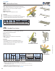
LPTA
NOP2X
NOP1
Typical LPTA
perpendicular installation
Typical LPTA
parallel installation
NOP4
Typical NOP4 installation
NOP Moisture Barrier Plates
Truss & Rafter
Moisture Barrier Plates protect the bottom chords of trusses from
moisture damage caused by direct contact with concrete. These plates
eliminate the need for more expensive treated wood plates.
Materials: See chart
Finish: G90 galvanizing
Codes: See page 11 for Code Reference Chart
Installation:
• Use all specied fasteners. See Product Notes, page 17.
• Pre-attach to truss bottom chord or rafter using pre-punched prongs
and/or 6d common nails to prevent wood-to-concrete contact.
Size Ref. No. W L Qty Type
NOP2X
TSS2, TBP8
26
1-7/16
8
-- --
-- --
NOP1
-- --
22
1-1/2
8
2
6d
4x
NOP4
TSS2-2
26
3-1/2
8
2
6d
1)
Nails
: 6d nails are 0.120" dia. x 2" long.
2x
Code
Ref.
120
Stock
No.
Steel
Gauge
Dimensions (in)
Fastener Schedule
1
LPTA Embedded Truss Anchors
Low prole design attaches to 2 x 4 or larger bottom chords and
provides uplift and lateral load resistance.
Materials: 18 gauge
Finish: G90 galvanizing
Codes: See page 11 for Code Reference Chart (Pending
ICC-ES ESR-2787)
Installation:
• Use all specied fasteners. See Product Notes, page 17.
• Embed LPTA 4" into concrete tie beam or masonry bond beam.
• Anchors should be spaced no closer than 8" center-to-center.
• Moisture barrier may be required.
Ref. No.
W
H Type
F1 F2 F3 F1 F2 F3
Perpendicular 1510 335 745 345 1510 280 745 345
Parallel 1470 750 1085 335 1470 750 975 280
1
)
Allowable loads have been increased 60% for wind or seismic loads; no further increase shall be
p
ermitted.
2
)
Minimum nail
p
enetration shall be 1-1/2" for 10d nails.
3
)
Grout or concrete com
p
ressive stren
g
th shall be 2500
p
si or
g
reater at 28 da
y
s.
4
)
Minimum
q
uantit
y
of fasteners to be installed. Product ma
y
have additional nail holes not needed to meet
p
ublished allowable load of
p
roduct.
5
)
The five nail holes nearest the embedment line must be filled to achieve the lateral loads listed in the table.
6
)
NAILS: 10d x 1-1/2" nails are 0.148" dia. x 1-1/2" lon
g
.
New
p
roducts or u
p
dated
p
roduct information are desi
g
nated in blue font.
Code
Ref.
F1618
Load
Direction
to Wall
Installation
Dimensions
(in)
10 10d x 1-1/2
Uplift
160%
Uplift
160%
Lateral 160%
Per Anchor
LPTA LTA2 5 8-1/4
S-P-F
Allowable
Loads (Lbs.)
1,3
Lateral 160%
USP
Stock No.
Steel
Gauge
Min
Qty.
4,5
Fastener
Schedule
2,6
DF/SP
Allowable Loads (Lbs.)
1,3
Uplift
Uplift
F1
F1
F3
F2
F1
F3
F2
L
L
1-7/16"
L
W
W
W
1-3/4"
H
W
4"