
Technical Specifications

49
Holdowns
© 2015 MiTek. All rights reserved.
PHD / PHDA Predeected Holdowns
Holdowns
Reduces eccentricity in the studs/post with decreased centerline
dimension. No thru-bolts to countersink.
Materials: See chart
Finish: G90 galvanizing
Codes: See page 11 for Code Reference Key Chart
Installation:
• Use all specied fasteners. See Product Notes, page 17.
• Place the PHD/PHDA over the anchor bolt. No washer
is required.
• Install with USP’s code evaluated WS3 (1/4" x 3")
Wood Screws, which are provided with the holdown.
• Tighten anchor bolt nuts nger tight, snug, to base, plus
1/3 to 1/2 additional turns with a wrench. To prevent loosening
of the anchor nut during critical loading, use a locking nut or
tighten a second nut over the rst to lock nuts in place.
• PHD/PHDA Predeected Holdowns may be installed
off sill plate with no load reduction.
• The design engineer may specify any alternate anchorage
calculated to resist the tension load for a specic application.
Anchorage exposure length should take the bearing plate
height of 1-5/8" into account, anchor bolt thread should
visibly extend above nut.
• If used to anchor a built-up post, such as a double 2 x 4, the
post component shall be designed to act as a single unit.
Holdown fasteners specied shall not be considered to
attach multiple plies together.
• For anchorage options see STBL Anchor Bolt section on
pages 34-35.
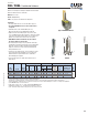
Typical PHD5A installation
PHD8
PHD5A
DF/SP S-P-F
Ref. No. W H D
CL
8
Qty Dia. Qty 160% 160%
PHD2A HDU2-SDS2.5 14 3 7-3/4 2-5/8 1-3/8 1 5/8 6 3215 2700 0.155
PHD4A HDU4-SDS2.5 14 3 9-3/4 2-5/8 1-3/8 1 5/8 10 5215 4380 0.137
PHD5A HDU5-SDS2.5 14 3 11-11/16 2-5/8 1-3/8 1 5/8 14 6525 5480 0.135
PHD8 HDU8-SDS2.5 12 3-1/4 16-1/2 3 1-3/8 1 7/8 24 8185 6875 0.062
1) Allowable loads have been increased 60% for wind and seismic loads; no further increase shall be permitted.
2) The designer must specify anchor bolt type, length, and embedment.
3) Deflections are derived from static, monotonic load tests of devices connected to DF-L wood members with specified fasteners.
4) The designer shall consider the effect of compression, bearing, tension, and combined bending due to device eccentricity when applicable.
5) The PHD/PHDA may be elevated off the sill.
6) WS3 wood screws are 1/4" x 3" and are included with PHD/PHDA models.
7) Minimum post thickness is 3". Consult USP for installations less than 3".
8) "CL" denotes the distance between the post and center of the anchor bolt.
30,
F31,
R16
USP
Stock No.
Steel
Gauge
Dimensions (in) Fastener Schedule
Allowable Tension Loads (Lbs.)
1,4,7
Anchor
Bolts
2
WS3 Wood
Screws
6
Code
Ref.
Deflection at
Allowable Load
Δ (in) at 160%
3,5
D
CL
H
W
1-5/8"