
Technical Specifications

161
© 2015 MiTek. All rights reserved.
EWP Hangers
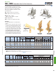
TMP / TMPH Adjustable Rafter-To-Plate Connectors
The TMP and TMPH are designed to make rafter-
to-plate connections and eliminate time-consuming
bird’s-mouth notching or bevel plate installation.
Both series are available in I-Joists sizes, as well
as standard 2x sizes.
TMP – Adjusts to pitches from 1/12 to 6/12.
TMPH – Adjusts to pitches from 6/12 to 14/12.
Ma terials: TMP – 18 gauge;
TMPH – 16 gauge, Fulcrum – 12 gauge
Finish: G90 galvanizing
Codes: See page 11 for Code Reference Chart
Installation:
• Use all specied fasteners. See Product Notes,
page 17.
• Position connector on top plate. Fasten connector
to outside of top plate with specied nails. Insert
rafter into rafter pocket. Adjust rafter and pocket
to correct pitch. Fasten rafter to connector with
specied nails. Installing the TMP requires driving
specied nails through the opposing slots in the
pocket. TMPH installation involves sliding the
fulcrum until it supports the pocket at the desired
pitch and nailing down through the fulcrum base
into the top plate to lock the fulcrum into position.
Typical TMPH
installation
Typical TMP
installation
TMPHTMP
Floor Uplift Floor Uplift
Rafter Width Ref. No. W L Qty Type Qty Type 100% 115% 125% 160% 100% 115% 125% 160%
1-1/2 TMP2 VPA2 18 1-9/16 5-9/16 6 10d 4 10d x 1-1/2 990 990 990 220 990 990 990 220
1-3/4 TMP175 VPA25 18 1-13/16 5-9/16 6 10d 4 10d x 1-1/2 1150 1150 1150 220 1150 1150 1150 220
2 or 2-1/8 TMP21
VPA2.06,
VPA2.1
18 2-1/8 6-3/8 6 10d 4 10d x 1-1/2 1290 1290 1290 220 1290 1290 1290 220
2-5/16 TMP23 VPA35 18 2-3/8 6-3/8 6 10d 4 10d x 1-1/2 1970 1970 1970 220 1970 1970 1970 220
2-1/2 or 2-5/8 TMP25 VPA3 18 2-11/16 6-3/8 6 10d 4 10d x 1-1/2 1970 1970 1970 220 1970 1970 1970 220
3 TMP31 -- -- 18 3-1/8 7-5/16 6 10d 4 10d x 1-1/2 1970 1970 1970 220 1970 1970 1970 220
3-1/2 TMP4 VPA4 18 3-9/16 7-5/16 6 10d 4 10d x 1-1/2 1970 1970 1970 220 1970 1970 1970 220
1) Allowable Loads are governed by test results; no further increase shall be permitted
2) Minimum nail penetration shall be 1-1/2" for 10d nails.
3)
NAILS:
10d x 1-1/2" nails are 0.148" dia. x 1-1/2" long, 10d nails are 0.148" dia. x 3" long.
New products or updated product information are designated in
blue font
.
6,
R11,
F3
Dimensions (in)
USP
Stock No.
Steel
Gauge
Roof
Code
Ref.
Fastener Schedule
2,3
Roof
Plate Rafter
DF/SP
Allowable Loads (Lbs.)
1
S-P-F
Allowable Loads (Lbs.)
1
Top Side Uplift
Rafter Width Ref. No. W H D L Qty Qty Type Qty Type 6/12 7/12 8/12 9/12 10/12 11/12 12/12 13/12 14/12 160%
1-1/2 TMPH2 VPA2 1-9/16 2-1/2 4 6-9/16 8 2 10d 8 10d x 1-1/2 3190 3290 3390 3140 2900 2710 2520 2230 1950 200
1-3/4 TMPH175 VPA25 1-13/16 2-3/8 4 6-9/16 8 2 10d 8 10d x 1-1/2 3190 3290 3390 3140 2900 2710 2520 2230 1950 200
2 or 2-1/8 TMPH21
VPA2.06,
VPA2.1
2-1/8 2-5/8 4 7-3/8 8 2 10d 8 10d x 1-1/2 3190 3290 3390 3140 2900 2710 2520 2230 1950 200
2-5/16 TMPH23 VPA35 2-3/8 2-1/2 4 7-3/8 8 2 10d 8 10d x 1-1/2 3190 3290 3390 3140 2900 2710 2520 2230 1950 200
2-1/2 or 2-5/8 TMPH25 VPA3 2-11/16 2-5/16 4 7-3/8 8 2 10d 8 10d x 1-1/2 3190 3290 3390 3140 2900 2710 2520 2230 1950 200
3 TMPH31 -- -- 3-1/8 2-11/16 4 8-9/16 8 2 10d 8 10d x 1-1/2 3190 3290 3390 3140 2900 2710 2520 2230 1950 200
3-1/2 TMPH4 VPA4 3-9/16 2-1/2 4 8-9/16 8 2 10d 8 10d x 1-1/2 3190 3290 3390 3140 2900 2710 2520 2230 1950 200
1) Allowable loads may not be increased for duration of load adjustments.
2) Minimum nail penetration shall be 1-1/2" for 10d nails.
3) Web stiffeners are required for all Wood I-Joist installations.
4)
NAILS:
10d x 1-1/2" nails are 0.148" dia. x 1-1/2" long, 10d nails are 0.148" dia. x 3" long.
New products or updated product information are designated in
blue font
.
6,
R11,
F3
Code
Ref.
According to Pitch
USP
Stock No.
Dimensions (in)
Fastener Schedule
2,3
Plate
Rafter
4
DF/SP
Allowable Loads (Lbs.)
1
3-1/2"
Pitch Range:
TMP - 1/12 – 6/12
TMPH - 6/12 – 14/12
L
W
W
EWP Hangers
L
D
4-11/16"
Fulcrum
H