
Technical Specifications

210
Plated Truss
© 2015 MiTek. All rights reserved.
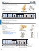
STC Truss Clips
STC
TR1T
Typical TR2 installation
TR2
TR1
The STC provides uplift resistance by securing trusses to top plates.
Slotted nail holes allow for horizontal movement as scissor trusses deect.
Materials: 12 gauge
Finish: G90 galvanizing
Codes: See page 11 for Code Reference Chart
Installation:
• Use all specied fasteners. See Product Notes, page 17.
• When installing, do not fully set nails.
• Locate nails into the center of slots to allow for horizontal movement.
Typical STC installation
Uplift
1
F1
Uplift
1
F1
Ref. No. Description W1 W2 Qty Type Qty Type 160% 160% 160% 160%
STC24 TC24 12 2 x 4 top plate 3-9/16 1-5/8 5 10d x 1-1/2 6 10d x 1-1/2 810 330 680 275
STC26 TC26 12 2 x 6 top plate 5-1/2 1-5/8 5 10d x 1-1/2 6 10d x 1-1/2 810 330 680 275
STC28 TC28 12 2 x 8 top plate 7-1/4 1-5/8 5 10d x 1-1/2 6 10d x 1-1/2 810 330 680 275
1) Uplift loads have been increased 60% for wind or seismic loads; no further increase shall be permitted.
2)
NAILS:
10d x 1-1/2" nails are 0.148" dia. x 1-1/2" long.
New products or updated product information are designated in
blue font
.
10,
R8,
F5
Code
Ref.
DF/SP
Allowable Loads (Lbs.)
S-P-F
Allowable Loads (Lbs.)
USP
Stock No.
Steel
Gauge
Fastener Schedule
2
Truss Plate
Dimensions (in)
Slotted design allows truss to deect without imposing
load on wall below.
Materials: See chart
Finish: G90 galvanizing
Codes: See page 11 for Code Reference Chart
Installation:
• Use all specied fasteners. See Product Notes, page 17.
• Do not fully set nails.
• Locate nails into the center of slots.
• Due to the potential for squeaks, the TR series products
are not recommended for oor applications.
TR Roof Truss Ties
F1
5
F2
F1
5
F2
F1
5
F2
Ref. No. Description Qty Type Qty Type 160% 160% 160% 160% 160% 160%
TR1 STC 18 single slot 1 8d 2 8d 85 50 35 35 -- -- -- --
TR1T STCT 16 single slot 1 8d 2 8d 240 -- -- 130 -- -- 80 -- --
TR2 DTC 18 double slot 2 8d 4 8d 125 210 85 135 -- -- -- --
1
)
Loads have been increased for short-term loadin
g
; no further increase allowed.
2
)
Truss must be bearin
g
on to
p
p
late to achieve the allowable loads under "Without Ga
p
".
3
)
Installed with maximum 1/4" s
p
ace between rafter or truss and to
p
p
late under "With 1/4" Ga
p
".
S
p
ace is not limited to 1/4", where loads are not re
q
uired.
4
)
Installed with maximum 1/2" s
p
ace between rafter or truss and to
p
p
late under "With 1/2" Ga
p
".
S
p
ace is not limited to 1/2", where loads are not re
q
uired.
5
)
To achieve F1 loads in both directions, cli
p
s must be installed on both sides of the truss and sta
gg
ered to avoid nail interference.
6
)
NAILS: 8d nails are 0.131" dia. x 2-1/2" lon
g
.
130
Code
Ref.
USP
Stock No.
Steel
Gauge
Fastener Schedule
6
Without Gap
2
With 1/4" Gap
3
Truss Plate
With 1/2" Gap
4
DF/SP
Allowable Loads (Lbs.)
1
1) Loads have been increased for short-term loading; no further increase allowed.
2) Truss must be bearing on top plate to achieve the allowable loads under "Without Gap".
3) Installed with maximum 1/4" space between rafter or truss and top plate under "With
1/4" Gap". Space is not limited to 1/4", where loads are not required.
4) Installed with maximum 1/2" space between rafter or truss and top plate under
"With 1/2" Gap". Space is not limited to 1/2", where loads are not required.
5) To achieve F1 loads in both directions, clips must be installed on both sides of
the truss and staggered to avoid nail interference.
6) NAILS: 8d nails are 0.131" dia. x 2-1/2" long.
F2
2-1/2"
2-3/4"
1-1/4"
1-1/4"
2"
F1
(see footnote #5)
Plated Truss
F1
1-1/4" slots
W2
W1
2-11/16"
1-7/8"
4-1/4"
1-3/4