
Use and Care Manual


194
Copyright © 2020 MiTek Industries, Inc. All Rights Reserved
Fire Wall Hangers
Fire Wall Hangers
MiTek
®
Product Catalog
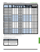
Ref. No. W H
2 x 8 FWH28 -- 1-9/16 7-1/8
2 x 10 FWH210 -- 1-9/16 9-1/8
2 x 12 FWH212 -- 1-9/16 11-1/8
1-3/4 x 9-1/2 FWH1795 DGHF1.81/9.5 1-13/16 9-7/16
1-3/4 x 11-7/8 FWH17118 DGHF1.81/11.88 1-13/16 11-13/16
1-3/4 x 14 FWH1714 DGHF1.81/14 1-13/16 13-15/16
1-3/4 x 16 FWH1716 DGHF1.81/16 1-13/16 15-15/16
2 - 2-1/8 x 9-1/2 FWH2095 DGHF2.1/9.5 2-1/8 9-7/16
2 - 2-1/8 x 11-7/8 FWH20118 DGHF2.1/11.88 2-1/8 11-13/16
2 - 2-1/8 x 14 FWH2014 DGHF2.1/14 2-1/8 13-15/16
2 - 2-1/8 x 16 FWH2016 DGHF2.1/16 2-1/8 15-15/16
2-5/16 x 9-1/2 FWH2395 DGHF2.37/9.5 2-3/8 9-7/16
2-5/16 x 11-7/8 FWH23118 DGHF2.37/11.88 2-3/8 11-13/16
2-5/16 x 14 FWH2314 DGHF2.37/14 2-3/8 13-15/16
2-5/16 x 16 FWH2316 DGHF2.37/16 2-3/8 15-15/16
2-5/16 x 18 FWH2318 DGHF2.37/18 2-3/8 17-15/16
2-5/16 x 20 FWH2320 DGHF2.37/20 2-3/8 19-15/16
2-1/2 x 9-1/2 FWH2595 DGHF2.56/9.5 2-9/16 9-7/16
2-1/2 x 11-7/8 FWH25118 DGHF2.56/11.88 2-9/16 11-13/16
2-1/2 x 14 FWH2514 DGHF2.56/14 2-9/16 13-15/16
2-1/2 x 16 FWH2516 DGHF2.56/16 2-9/16 15-15/16
2-1/2 x 18 FWH2518 DGHF2.56/18 2-9/16 17-15/16
2-1/2 x 20 FWH2520 DGHF2.56/20 2-9/16 19-15/16
3-1/2 x 9-1/2 FWH3595 DGHF3.62/9.5 3-9/16 9-7/16
3-1/2 x 11-7/8 FWH35118 DGHF3.62/11.88 3-9/16 11-13/16
3-1/2 x 14 FWH3514 DGHF3.62/14 3-9/16 13-15/16
3-1/2 x 16 FWH3516 DGHF3.62/16 3-9/16 15-15/16
3-1/2 x 18 FWH3518 DGHF3.62/18 3-9/16 17-15/16
3-1/2 x 20 FWH3520 DGHF3.62/20 3-9/16 19-15/16
3-1/2 x 22 FWH3522 DGHF3.62/22 3-9/16 21-15/16
3-1/2 x 24 FWH3524 DGHF3.62/24 3-9/16 23-15/16
MiTek USP
Stock No.
Joist
Size (in)
Dimensions (in)
Code
Ref.
IBC,
FL,
LA
FWH Fire Wall Hangers
Continued on next page
Geometry Table
The Fire Wall Hanger is designed for attaching truss, I-joist, solid sawn lumber,
or engineered wood oor framing members to double wall top plates or minimum
2-ply 2x solid sawn header re rated wood frame walls. The advanced design
allows the installation of the FWH before the 5/8" gypsum wallboard (drywall)
is attached and permits the building project to be completely framed-up, and
weather-tight before the gypsum wallboard sheathing work starts.
Materials: 14 gauge
Finish: G90 galvanizing
Options: See Specialty Options chart on page 195
Codes: IBC, FL, LA
Patents: U.S. Patent No. 10,316,510
Installation:
• Install the face of hanger anges tight to stud wall framing.
• For typical installations, the FWH does not need to be installed at stud
locations. An increase in capacity can be achieved by installing the FWH
at a stud. See the Allowable Load Table on page 195.
• The end of the truss/joist should measure 1-5/8" from the face of the
supporting wall. See Figure 1.
• The truss/joist should bear fully on the FWH seat with a gap no greater than
1/8" between the end of the supported member and the hanger. See Figure 1.
• Gypsum Wallboard Installation – Use the FWH-T template to slot cut the
gypsum wallboard. See FWH-T Template Sequence. Slide the gypsum
wallboard into position and fasten to the framing members meeting the
minimum requirements specied by code.
FWH
H
2"
2-1/4"
W
FWH hangers are tested per ASTM E814 standards. When installed on one
side of a maximum 2 hour fire-rated wall assembly, the penetration of
the MiTek FWH Fire Wall Hanger through the gypsum wallboard will not
reduce the fire resistive rating of the 2 hour fire resistive assembly.
2 Hour Fire-Rating
1/8"
1-5/8"
Figure 1
Typical FWH Side View
5-3/4"
FWH-T template
(must be ordered separately)
8"
13"
1) Align the FWH-Template
slot with the mark in the
gypsum wallboard and
engage the prongs
into edge of gypsum
wallboard
Edge Prong
3) Run the gypsum
wallboard cutter
down the template
to cut the slot
2) Rotate the template
and press down on
the end to engage
the corner prongs
Corner Prong
FWH-T Template Installation Sequence
2-3/4"