
Use and Care Manual


250
Copyright © 2020 MiTek Industries, Inc. All Rights Reserved
Truss & Rafter
Truss & Rafter
MiTek
®
Product Catalog
Type
11
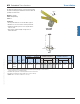
TA12 -- 14 1 6-3/4 5 10d x 1-1/2 990 245 335 1980 490 670
TA14 -- 14 1 8-3/4 7 10d x 1-1/2 1205 245 335 2410 490 670
TA14R -- 14 1 8-3/4 7 10d x 1-1/2 1205 245 335 2410 490 670
TA16 -- 14 1 10-3/4 8 10d x 1-1/2 1205 245 335 2410 490 670
TA16R -- 14 1 10-3/4 8 10d x 1-1/2 1205 245 335 2410 490 670
TA18 -- 14 1 12-3/4 8 10d x 1-1/2 1205 245 335 2410 490 670
TA18R -- 14 1 12-3/4 8 10d x 1-1/2 1205 245 335 2410 490 670
TA20 -- 14 1 14-3/4 8 10d x 1-1/2 1205 245 335 2410 490 670
TA20R -- 14 1 14-3/4 8 10d x 1-1/2 1205 245 335 2410 490 670
TA22 -- 14 1 16-3/4 8 10d x 1-1/2 1205 245 335 2410 490 670
TA22R -- 14 1 16-3/4 8 10d x 1-1/2 1205 245 335 2410 490 670
TA24 -- 14 1 18-3/4 8 10d x 1-1/2 1205 245 335 2410 490 670
TA24R -- 14 1 18-3/4 8 10d x 1-1/2 1205 245 335 2410 490 670
TA36 -- 14 1 30-3/4 8 10d x 1-1/2 1205 245 335 2410 490 670
1) Allowable loads have been increased 60% for wind or seismic loads; no further increase shall be permitted.
2) Allowable loads are based on anchorage to masonry/uncracked concrete.
3) DF Allowable Loads are identical to all SP Allowable Loads listed in the chart.
4) Minimum specified masonry or concrete compressive strength, f'm is 1,500 psi and f'c is 2,500 psi at 28 days respectively.
5) Allowable loads require a No. 4 rebar through the shear cones of the anchors.
6) "R" after TA models indicates truss anchors with riveted moisture barrier as in TA12R.
7) Minimum quantity of fasteners to be installed. Product may have additional nail holes not needed to meet published allowable load of product.
8) Height (H) is the distance the anchor extends out of concrete or masonry.
9) Double anchor installation is permitted on 1-ply roof members when anchors are offset from each other a minimum of 3/4".
Do not install anchors directly back-to-back or nails will interfere with each other.
10) Allowable uplift capacity for TA models installed with (4) 10d x 1-1/2" nails is 780 lbs per anchor. Lateral loads do not apply.
11)
NAILS:
10d x 1-1/2 nails are 0.148" dia. x 1-1/2" long.
Dimensions (in)
Fastener
Schedule
H
8
(Out of
Concrete)
Per Anchor
SP
Allowable Loads (Lbs.)
1,2,3,4,5
Single Anchor
Double Anchor
9
Code
Ref.
--
MiTek USP
Stock No.
6
Steel
Gauge W
Min
Qty.
7
F2
160%
Uplift
160%
10
F1
160%
F2
160%
Uplift
160%
10
F1
160%
Ref.
No.
TA20R
TA18
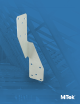
TA / TAR Embedded Truss Anchors
H
4"
Embedment
W
1-1/2"
1" Typ.
4"
Embedment
H
8-1/2"
W
1-1/2"
1"
Typical TA18
installation
Typical TA16R
installation
Moisture
barrier
seat
TA – Anchors are rated for both uplift and lateral loads. They can be
installed straight or eld-bent around truss or rafter members. An
embossed embedment line assures accurate embedment depth.
TAR – Riveted anchors provide a moisture barrier in addition to
uplift and lateral resistance all in one product.
Materials: 14 gauge
Finish: G90 galvanizing
Installation:
• Use all specied fasteners. See Product Notes, page 18.
• Embed 4" into concrete tie beam or masonry bond beam.
• For double anchor installations: anchors should be installed on opposite
sides of wood member and offset a minimum 3/4" from each other in bond
beam or concrete tie beam. See increased design values in chart below.
• Designer may specify alternative nailing schedules. Refer to Nail
Specication table on page 23 for nail shear values, load values shall
not exceed published allowable loads.
• When using alternative nailing schedules, lower-most holes in strap
shall be lled progressing upward towards the top of the strap.
• Straps may be installed straight or wrapped over to achieve table loads.
• Moisture barrier will be required in installations unless
another moisture remediation method is used.
F1
F1
F2
F2
Uplift
F1
F1
F2
F2
Uplift