
Use and Care Manual


258
Copyright © 2020 MiTek Industries, Inc. All Rights Reserved
Truss & Rafter
Truss & Rafter
MiTek
®
Product Catalog
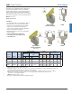
MUGT Girder Tiedown
Designed for higher uplift resistance for wood frame construction.
The MUGT15 can accommodate variable truss bearing depths.
Materials: 12 gauge
Finish: G90 galvanizing
Codes: IBC, FL, LA
Installation:
• Use all specied fasteners. See Product Notes, page 18.
• When straps are wrapped over the truss, install nails in backside
of truss. See MUGT15 installation diagram for minimum nail
requirements into the face and on top of the truss.
• If installed straight-up with no wrap over the top of the truss,
ll all nail holes.
• Moisture barrier may be required.
Ref. No. Qty Type
Uplift 160%
1
Uplift 160%
1
Face-Max 1 5/8 -- 28 -- 10d
4240 3730
Top-Min 1 5/8 4 6 12 10d
3945 3160
1) Allowable loads have been increased 60% for wind or seismic loads; no further increase shall be permitted.
2) Additional anchorage products to be designed by others.
3) Designer must specify anchor bolt type, length, and holdown device.
4)
NAILS:
10d nails are 0.148" dia. x 3" long.
New products or updated product information are designated in
blue font
.
Mounting
Condition
MiTek USP
Stock No.
Steel
Gauge
S-P-F
Allowable
Loads (Lbs.)
IBC,
FL, LA
MUGT15 MGT 12
DF/SP
Allowable
Loads (Lbs.)
Fastener Schedule
2
Rod/Bolt
3
Rafter/Truss
4
Top
Qty
Face
Qty
Back
Qty
Dia
(in)
Wood-To-Wood Installation
Code
Ref.
Typical MUGT15
top-min installation
with PHD4A
Typical MUGT15
connection to support beam
MUGT15
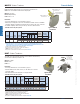
HUGT Girder Tiedowns
The HUGT series high uplift girder tiedowns can be installed
on beams and top chords of trusses with slopes from 0˚ to 34˚.
Materials: 7 gauge
Finish: Primer
Codes: FL
Installation:
• Use all specied fasteners. See Product Notes, page 18.
• Install the HUGT over the beam or truss (see “W” dimension
on chart for appropriate width).
• Install (4) LBP58-TZ washers for (2) 5/8" tension rod/bolts.
• Attached members shall be designed to resist applied loads.
• Moisture barrier may be required.
Typical HUGT3
installation with HTT45’s
HUGT
Ref. No. Qty Type Qty Qty Type
HUGT2 HGT-2 7 3-5/16 5-3/4 4 LBP58-TZ 2 5/8 8 10d
9575 6925
HUGT3 HGT-3 7 4-15/16 7-3/8 4 LBP58-TZ 2 5/8 8 10d 9860
7805
HUGT4 HGT-4 7 6-7/8 9 4 LBP58-TZ 2 5/8 8 10d 9860
7790
1) Allowable loads have been increased 60% for wind or seismic loads; no further increase shall be permitted.
2) Listed loads apply where roof pitch is between 3:12 and 8:12.
3) Additional anchorage products to be designed by others.
4) Designer must specify anchor bolt type, length, and holdown device.
5)
NAILS:
10d nails are 0.148" dia. x 3" long.
New products or updated product information are designated in
blue font
.
FL
Girder
DF/SP
Allowable
Loads (Lbs.)
1,2
S-P-F
Allowable
Loads (Lbs.)
1,2
Uplift
160%
Uplift
160%
Wood-to-Wood Installation
Code
Ref.
MiTek USP
Stock No.
Steel
Gauge
Anchor
Washers
Threaded
Rod
Dia
(in)
W
(in)
O.C. Dim
Between
Anchors
(in)
Fastener Schedule
3,5
14-5/8"
1-1/4"
3-11/16"
2-7/16"
(4) LBP58-TZ washers
are required for
5/8" dia. bolt.
(washers not included).
2-3/16"
W
4"
2-7/8"
PHD4A
page 66
Install a minimum
of (4) 10d nails
into the top
Install a minimum of (12) 10d
nails into back
Install a minimum
of (6) 10d nails
into the face
HTT45
(not included)
see page 70
Min 3" x 3" x 1/4"
Bearing Plate
Support beam
designed by others
1-1/4"
Install a minimum
of (4) 10d nails
into the top
Install a minimum of (12) 10d
nails into back
Install a minimum
of (6) 10d nails
into the face
MUGT15
5/8" bolt