
Use and Care Manual


50
Copyright © 2020 MiTek Industries, Inc. All Rights Reserved
Concrete & Masonry
Concrete & Masonry
MiTek
®
Product Catalog
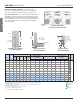
STB / STBL Anchor Bolts
Ref. No. Dia. L H Midwall Corner End Wall Midwall Corner End Wall Midwall Corner End Wall
STB16 SSTB16 6 5/8 17-13/16 5 12-13/16 4230 4230 4230 4230 4230 4230 3525 3525 3525
STB20 SSTB20 6 5/8 21-13/16 5 16-13/16 5120 4740 4740 5115 4230 4230 4265 3555 3555
STB24 SSTB24 6 5/8 25-13/16 5 20-13/16 5990 5915 5915 5990 5570 5570 4990 4675 4675
STB28 SSTB28 8 7/8 31 5 26 10100 9490 9490 9110 9110 9110 7650 7650 7650
STB34 SSTB34 8 7/8 36 6 30 11415 10525 10250 11390 10525 9405 9515 8770 7900
STB36 SSTB36 8 7/8 38 8 30 11415 10525 10250 11390 10525 9405 9515 8770 7900
STBL16 SSTB16L 6 5/8 19-9/16 6-3/4 12-13/16 4230 4230 4230 4230 4230 4230 3525 3525 3525
STBL20 SSTB20L 6 5/8 23-9/16 6-3/4 16-13/16 5120 4740 4740 5115 4230 4230 4265 3555 3555
STBL24 SSTB24L 6 5/8 27-9/16 6-3/4 20-13/16 5990 5915 5915 5990 5570 5570 4990 4675 4675
STBL28 SSTB28L 8 7/8 32-3/4 6-3/4 26 10100 9490 9490 9110 9110 9110 7650 7650 7650
1
)
Loads may not be increased for short term loadin
g
.
2
)
Minimum center to center spacin
g
between bolts is 3
(
E
)
for anchors actin
g
in tension simultaneously.
3
)
Minimum ed
g
e distance is 1-3/4".
4
)
Concrete stemwall shall be a minimum of 6" thick for 5/8" anchor bolts and 8" for 7/8" anchor bolts.
5
)
End distance shall be no less than 5".
6
)
Connection is limited by lowest of bolt or holdown capacity.
7
)
Concrete block shall be minimum 10" block.
8
)
See ICC-ES ESR-2266 for additional information.
IBC,
FL,
LA
MiTek
Stock No.
Stem-
wall
Width
Min.
Embed
(E)
Corrosion
Finish
Allowable Tension Loads (Lbs)
1,2
Code
Ref.
Dimensions (in)
ASCE Seismic Design
Category A&B
ASCE Seismic Design
Category C - F
Wind
Corrosion Finish
Stainless Steel Gold Coat
HDG Triple Zinc
Corrosion Finish Stainless Steel Gold Coat HDG Triple Zinc
Corrosion
Finish
Stainless Steel
Gold Coat
HDG
Triple Zinc
Plan view of STB/STBL
placement in concrete stemwall
Corner
installation
45°
45° 45°
Corner
installation
135°
Anchor bolt
(typ)
Non-corner
installation
135°/90°/45°
0°
Outside edge
of concrete
Plan view along continuous
stem wall installation
Plan view of end of
stem wall installation
Plan view of corner of
stem wall installation
Place STB
angle diagonal in
corner application
Install @ 45°
from edge of
stem wall and
orientated away
from end of stem
wall
12" min return
5"
1-3/4" min
1-3/4" min
#4 Rebar
Locate approx.
45° from wall
2 x E min.
rebar
length
2 x E min.
rebar
length
2 x E min.
rebar
length
5"
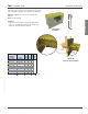
Monolithic or Stem Wall Foundations – Prior to pour, install the
STB or STBL in an upright position and at a 45° angle to the wall. Install
one horizontal #4 rebar at a depth of 4" (minimum). (See illustrations.)
Concrete Block Applications – Prior to cell pour, install the STB or STBL in
an upright position and at a 45° angle to the wall. (See illustrations.) Use the
embossed angle guide on the end of the STB or STBL shaft as a guide. Install
one horizontal #4 rebar at a depth of 4" and one vertical #4 rebar maximum
48" o.c. spacing. Fill all cells with concrete having a minimum 2,500 psi
compressive strength.