
Use and Care Manual


62
Copyright © 2020 MiTek Industries, Inc. All Rights Reserved
Concrete & Masonry
Concrete & Masonry
MiTek
®
Product Catalog
KGLBT
Structural tee
12"
4"
3-1/2"
1-1/4"
T
3"
L
D
3"
1-1/2"
W
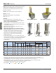
KGLB / KGLBT / KHGLB Laminated Beam Seats
KGLB – Single bolt, bearing only
KGLBT – Double bolt with structural tee provides uplift and
horizontal resistance
KHGLB – Double bolt design provides uplift and horizontal resistance
Materials: Flanges – 1/4" steel
Bearing Plate – See chart for “T” dimension
Anchor Dowels – 3⁄4" x 12" rebar
Finish: Primer
Options: Consult MiTek for non-catalog variations.
Installation:
• Use all specied fasteners. See Product Notes, page 18.
• Bolt holes shall be a minimum of 1⁄32" to a maximum of 1⁄16" larger
than the bolt diameter.
• Concrete or masonry walls must be checked by a design professional for
adequacy to resist lateral or uplift loads transferred from the beam seat anchor.
Typical KGLB installation
F2
3,4
Uplift 160
3
Ref. No. D L T Qty Dia. 5-1/8 6-3/4 8-3/4 10-3/4 160%
KHGLBA HGLBA 3-1/4 to 9 5 10 3/8 2 3/4 18750 11790 15525 20125 -- 9870 3905
KHGLBB HGLBB 3-1/4 to 9 6 10 3/8 2 3/4 22500 14145 18630 24150 -- 9870 3905
KHGLBC HGLBC 3-1/4 to 9 7 10 3/8 2 3/4 26250 16505 21735 28175 -- 9870 3905
KHGLBD HGLBD 3-1/4 to 9 8 10 3/8 2 3/4 30000 18860 24840 32200 -- 9870 3905
KGLBT512 -- 3-1/4 to 11 5-1/4 12 5/16 2 3/4 24750 12965 17080 22140 27200 9870 3905
KGLBT612 -- 3-1/4 to 11 6-1/2 12 3/8 2 3/4 29250 15325 20185 26165 32145 9870 3905
KGLBT516 -- 3-1/4 to 15 5-1/4 16 5/16 2 3/4 27200 12965 17080 22140 27200 9870 3905
KGLBT616 -- 3-1/4 to 15 6-1/2 16 3/8 2 3/4 32145 15325 20185 26165 32145 9870 3905
KGLBT520 -- 3-1/4 to 19 5-1/4 20 5/16 2 3/4 27200 12965 17080 22140 27200 9870 3905
KGLBT620 -- 3-1/4 to 19 6-1/2 20 3/8 2 3/4 32145 15325 20185 26165 32145 9870 3905
1) Beams must fully bear on plates.
2) The loads on concrete are based on allowable wood bearing stress perpendicular to the grain of 460 psi and actual beam
width times beam bearing length.
3) Allowable loads have been increased 60% for wind or seismic loads and are based on bolt in wood values only.
Loads assume concrete or masonry structure is adequate to resist loads in those directions.
4) Loads must be be reduced if the allowable lateral load (F2) for masonry or concrete column governs.
5) Designer shall specify minimum edge and spacing requirements in masonry or concrete structure.
--
Allowable Bearing Loads (Lbs.)
1,5
On Concrete with
Beam Width
2
Masonry
@ 375 psi
Min. 3-1/8
Beam
Width (W)
MiTek USP
Stock No.
Range
W
Dimensions (in)
Code
Ref.
Bolt
Schedule
Ref. No. W L T D Qty Dia.
Concrete
3
KGLB5A GLB5A 5-1/4 7 1/4 5 1 5/8 11790 11790
KGLB5B GLB5B 5-1/4 7 3/8 6 1 5/8 14145 14145
KGLB5C GLB5C 5-1/4 7 3/8 7 1 5/8 16505 16505
KGLB5D GLB5D 5-1/4 7 3/8 8 1 5/8 18860 18860
KGLB7A GLB7A 6-7/8 9 1/4 5 1 3/4 15525 15525
KGLB7B GLB7B 6-7/8 9 3/8 6 1 3/4 18630 18630
KGLB7C GLB7C 6-7/8 9 3/8 7 1 3/4 21735 21735
KGLB7D GLB7D 6-7/8 9 3/8 8 1 3/4 24840 24840
1) Beams must fully bear on plates.
2) The loads are based on the bearing value listed times the bearing area equal to W x D. (Note that full
bearing plate area is not used.) Bearing loads shall be reduced where limited by wood bearing on the plate.
3) The loads on concrete are based on allowable wood bearing stress perpendicular to the
grain of 460 psi and actual beam width times beam bearing length.
4) Designer shall specify minimum edge and spacing requirements in masonry or concrete structure.
5) Concrete or masonry support structure is assumed adequate to support loads listed.
--
Dimensions (in)
Allowable Bearing Loads (Lbs.)
1,4,5
MiTek USP
Stock No.
Masonry
@ 375 psi
2
Code
Ref.
Bolt
Schedule
1/2" min clearance
Bearing plate
Concrete pilaster
Rebar welded to
bearing plate
KGLB
3"
W
D
3-1/2"
L
T
12"
KHGLB
3"
3"
1-1/2"
1-1/4"
T
2-1/2"
2-1/2"
L
D
W
KGLB Load Table
KHGLB / KGLBT Load Table
Uplift
F2F2