
Technical Specifications
177
Truss & Rafter
© 2015 MiTek. All rights reserved.
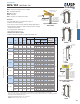
UGTS / USC Uplift Girder Ties
UGTS – 2-bolt shorter design when space is limited.
USC – 4-bolt high load design.
Materials: 10 gauge
Finish: USP primer
Codes: See page 11 for Code Reference Chart
Installation:
• Use all specied fasteners. See Product Notes, page 17.
• Bolts must be ordered separately.
• Place connector over truss or rafter and fasten with specied fasteners.
• Designer shall be responsible for design of masonry structure, including
any required reinforcement.
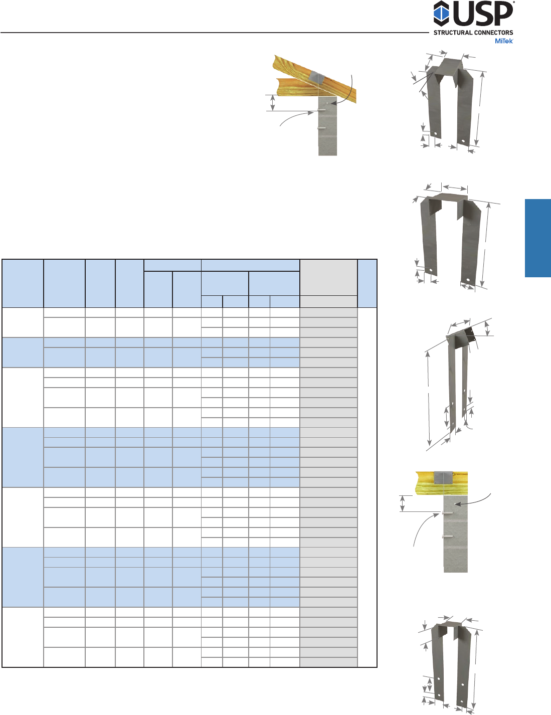
• For 2 ply applications, add ller block.
• Works with heel heights up to 14".
• Moisture barrier may be required.
• Bolts must be ordered separately. See page 24 for available sizes.
UGTS63
USC53
Typical USC53 installation
UGTS Similar
Typical USC3F installation
UGTS similar
UGTS4F
USC3F
Description Ref. No. W H Qty Type Qty Bolt Dia.
160%
UGTS3F -- -- 10 4-3/4 23 8 16d 2 3/4 7813
8 16d 2 3/4 7813
8 16d 4 3/4 10133
UGTS4F -- -- 10 6-1/2 23 8 16d 2 3/4 7813
8 16d 2 3/4 7813
8 16d 4 3/4 10133
UGTS43 -- -- 10 4-3/4 23 8 16d 2 3/4 7813
UGTS44 -- -- 10 6-1/2 23 8 16d 2 3/4 7813
8 16d 2 3/4 7813
8 16d 4 3/4 10133
8 16d 2 3/4 7813
8 16d 4 3/4 10133
UGTS53 -- -- 10 4-3/4 23 8 16d 2 3/4 7813
UGTS54 -- -- 10 6-1/2 23 8 16d 2 3/4 7813
8 16d 2 3/4 7813
8 16d 4 3/4 10133
8 16d 2 3/4 7813
8 16d 4 3/4 10133
UGTS63 -- -- 10 4-3/4 23 8 16d 2 3/4 7813
UGTS64 -- -- 10 6-1/2 23 8 16d 2 3/4 7813
8 16d 2 3/4 7813
8 16d 4 3/4 10133
8 16d 2 3/4 7813
8 16d 4 3/4 10133
UGTS73 -- -- 10 4-3/4 23 8 16d 2 3/4 7813
UGTS74 -- -- 10 6-1/2 23 8 16d 2 3/4 7813
8 16d 2 3/4 7813
8 16d 4 3/4 10133
8 16d 2 3/4 7813
8 16d 4 3/4 10133
UGTS83 -- -- 10 4-3/4 23 8 16d 2 3/4 7813
UGTS84 -- -- 10 6-1/2 23 8 16d 2 3/4 7813
8 16d 2 3/4 7813
8 16d 4 3/4 10133
8 16d 2 3/4 7813
8 16d 4 3/4 10133
1
)
U
p
lift loads have been increased 60% for wind or seismic loads; no further increase shall be
p
ermitted.
2
)
Use Powers Fasteners 3/4" - 6" Wed
g
e Bolts; or e
q
ual, installed in accordance with manufacturer's s
p
ecifications.
3
)
Fasteners shall be installed to full
y
g
routed and reinforced concrete masonr
y
or reinforced concrete
(
f'c = 2,500
p
si at 28 da
y
s
)
.
4
)
Bolts shall conform to ASTM A 307 or better.
5
)
Minimum nail embedment shall be 1-5/8" for 16d nails.
6
)
NAILS: 16d nails are 0.162" dia. x 3-1/2" lon
g
.
8/12 pitch
4-3/4 USC43 -- --
USC74 -- --
4-3/4
4-3/4
6-1/2
10
-- --
6-1/2
Code
Ref.
30-1/2
30-1/2
30-1/2
30-1/2
30-1/2
F23
DF/SP
Allowable Uplift
Loads (Lbs.)
1
30-1/2
30-1/2
30-1/2
Fastener Schedule
2,3,4,6
Concrete/
Masonry Wall
Rafter/ Truss
5
10
6-1/2
Dimensions (in)
10
10
10
10
4-3/4
30-1/2
30-1/2
4-3/4 30-1/2
6-1/2
6-1/2
10
4-3/4
USC84 -- --
USC83 -- --
10
10
10
USC73
USP
Stock No.
Steel
Gauge
30-1/26-1/210
USC3F -- -- 10
USC4F -- --
3 Ply Flat
4 Ply Flat
USC53
-- --
-- --
USC63
USC64
-- --
-- --
-- --
4/12 pitch
5/12 pitch
6/12 pitch
7/12 pitch
USC44
USC54
4"
2"
1-1/2"
Pitch
4/12 –
8/12
7-1/2 min
edge distance
7-1/2 min
edge distance
Lintel Block with (1) #5
continuous rebar
Lintel Block
with (1) #5
continuous
rebar
8" concrete block
with minimum (1)
#5 rebar each cell
continuous to footing
with standard hook at
bolt locations
8" concrete block
with minimum
(1) #5 rebar each
cell continuous
to footing with
standard hook at
bolt locations
3/4" bolts. Use 2 or 4
as required for uplift
3/4" bolts. Use 2 or 4
as required for uplift
H
6"
W
W
6"
2"
4"
4"
7-1/2"
Pitch 4/12"
- 8/12"
2-1/2"
W
2"
1-1/2"
H
Truss & Rafter
H
6"
H
6"
W
7-1/2"
2-1/2"
4"
2"