
Use and Care Manual

323
Specialty Options
Copyright © 2020 MiTek Industries, Inc. All Rights Reserved
Specialty Options
MiTek
®
Product Catalog
Top Flange Hanger Nailer Options
Continued on next page
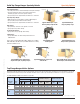
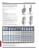
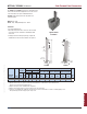
Solid Top Flange Hanger Specialty Details
Typical PHXU hanger
saddle option
Typical HLBH hanger sloped down,
skewed right, center ush shown
Typical HLBH hanger
ridge, top ange slope
Typical HLBH hanger top
ange offset, right shown
Typical HLBH hanger sloped seat,
down shown
Typical HLBH hanger skewed right,
sloped down right, top ange sloped
Sloped/Skewed Hanger:
• See nailing notes above for both Skewed Hanger and Sloped Seat Hanger.
• Specify skew and slope angles as well as skew/slope directions,
and skew type (square cut or bevel cut) when ordering.
• Specify if hanger is to be high side ush, low side ush, or center ush.
Sloped Top Flange Hanger:
• Additional nail holes may be added to top angle by MiTek designer.
• Specify top ange slope and direction when ordering.
• Specify if hanger is to be high side ush, low side ush, or center ush.
Ridge Hanger:
• Specify ush top of beam at center, right side, or left side.
• Specify angle of slope when ordering.
Top Flange Offset Hanger:
• Specify offset, left (L) or right (R), when ordering.
Saddle Hanger:
• Specify saddle width, “SA” when ordering. Allow clearance for
saddled member.
Refer to options for HLBH, KGLS, KGLT, KHGLS, KHGLT series or HWUH,
KHW, PHM, PHXU, SW, SWH series Special Order Worksheet for ordering
instructions at MiTek-US.com.
Typical HLBH hanger sloped
down top ange, right shown
Specify angle
W1
H1
SA
W2
H2
Plumb
height
Specify
angle
Joist
height
Specify angle
High side ush
Center ush
Low side ush
Slope
angle
Skew
angle
Skew
angle
Slope
angle
Specify angle
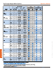
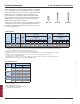
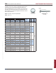
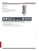
MiTek-USP Top Mount Hangers have been tested installed to various nailers. Wood nailers may be installed to the top of steel beams, concrete and
masonry walls. The table below represents maximum allowable loads for common top mount hangers installed on 2x, 2-ply 2x, 3x and 4x nailers.
For additional Nailer Installation information see page 203.
Type
5,6
Qty Type
5,6
2x 4 2 10d x 1-1/2 4 10d x 1-1/2 2080 230 1790 200
3x 4 4 16d x 2-1/2 4 10d x 1-1/2 2360 535 2030 460
(2) 2x 4 4 10d 4 10d x 1-1/2 2310 535 1985 460
4x 4 4 16d 4 10d x 1-1/2 2245 535 1930 460
2x 6 2 10d x 1-1/2 10 16d 2540 -- 2135 --
3x 6 6 16d x 2-1/2 10 10d 4500 -- 3780 --
(2) 2x 6 8 10d 10 16d 4140 1610 3480 1350
4x 6 10 16d 10 16d 5745 1610 4825 1350
SPF/HF
Allowable Loads (Lbs.)
1
Top
Qty
Face
Qty
Nailer Joist
Download
100%
Uplift
160%
2
Download
100%
Uplift
160%
2
Fastener Schedule
BPH
HBPH
DF/SP
Allowable Loads (Lbs.)
1
MiTek USP
Series
Nailer
Size