
Use and Care Manual

347
MH Connectors
Manufactured Housing Connectors
Copyright © 2020 MiTek Industries, Inc. All Rights Reserved
MiTek
®
Product Catalog
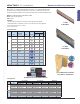
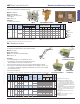
Connects 2x framing with oor sheathing up to 5/8".
Materials: 20 gauge
Finish: G90 galvanizing
Options: See chart for Corrosion
Finish Options
Codes: IBC, FL, LA
Installation:
• Use all specied fasteners.
Typical MP4F installation
Alternate FA3
installation
Qty Type Qty Type 100% 115% 125% 160% 100% 115% 125% 160%
6 8d x 1-1/2 6 8d x 1-1/2 V 590 670 720 750 505 575 615 645
6 8d x 1-1/2 6 8d x 1-1/2 H 590 670 720 750 505 575 615 645
6 8d x 1-1/2 6 8d x 1-1/2 V 590 670 720 750 505 575 615 645
6 8d x 1-1/2 6 8d x 1-1/2 H 585 585 585 585 505 575 615 645
1) Allowable loads have been increased 60% for wind or seismic loads; no further increase shall be permitted.
2) Refer to drawings for installation type and definition of the various load directions.
3) If installing over plywood, use 8d common nails for 100% of table load.
4) 8d common ( 0.131" dia. x 2-1/2" long) nails may be substituted for 8d x 1-1/2" nails with no allowable load reduction.
5)
NAILS:
8d x 1-1/2 nails are 0.131" dia. x 1-1/2" long.
S-P-F
Allowable Loads (Lbs.)
1,3
Steel
Gauge
Direction
of Load
2
Code
Ref.
IBC,
FL,
LA
Ref.
No.
MP4F LTP4 20
Type 1
Type 2
MiTek USP
Stock No.
Installation
Type
2,4
Joist or PlateHeader or Stud
Corrosion
Finish
Fastener Schedule
4,5
DF/SP
Allowable Loads (Lbs.)
1,3
Stud
Qty Type Concrete
5
Uncracked
1350 750 1015
Cracked
945 525 710
Uncracked
1350 750 1015
Cracked
945 525 710
Uncracked
-- 515 --
Cracked
-- 475 --
Uncracked
1120 550 890
Cracked
830 460 625
Uncracked
1120 550 890
Cracked
830 460 625
Uncracked
--
515 --
Cracked
--
405 --
1
)
Predrilled holes are not re
q
uired.
2
)
Allowable Stress Desi
g
n
(
ASD
)
values have been ad
j
usted for a load duration factor, CD, of 1.6 corres
p
ondin
g
to a ten-minute
load duration
(
i.e. wind or earth
q
uake loadin
g)
in accordance with the NDS. The ASD loads do not a
pp
l
y
to loads of other durations.
3
)
Allowable loads are based on a minimum stemwall thickness of 6", minimum distance from the end of the concrete
wall of 4" and minimum anchor s
p
acin
g
of 8".
4
)
U
p
lift deformation based on wood connection stren
g
th.
5
)
Minimum concrete stren
g
th f'c = 2,500
p
si.
6
)
NAILS: 10d x 1-1/2 nails are 0.148" dia. x 1-1/2" lon
g
.
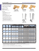
64 -- 10d x 1-1/2
2 --
10d x 1-1/2
One-Tab-Up
4
22
Plate
Size
Single
2x
10d x 1-1/2 6
10d x 1-1/2 6
Wind and ASCE Seismic Design A & B
Steel
Ga.
Single
3x
6
22-- FA3 216
FA3 -- 16 2
Single
3x
Single
2x
2
Standard
Standard
Installation
Type
ASCE Seismic Design C-F
Standard2 4 --
2 4 --
One-Tab-Up
Standard
Side
Qty
Top
Qty
Min
Stemwall
Thickness
(in)
Code
Ref.
MiTek
Stock
No.
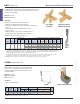
F1
160%
F2
160%
DF/SP
Allowable Loads (Lbs.)
2,3,4
Sill Plate
Fastener Schedule
1,6
Corrosion
Finish
Uplift
160%
Ref.
No.
IBC,
FL,
LA
--
IBC,
FL,
LA
--
1) Predrilled holes are not required.
2) Allowable Stress Design (ASD) values have
been adjusted for a load duration factor, CD, of
1.6 corresponding to a ten-minute load duration
(i.e. wind or earthquake loading) in accordance
with the NDS. The ASD loads do not apply to loads
of other durations.
3) Allowable loads are based on a minimum stemwall
thickness of 6", minimum distance from the end
of the concrete wall of 4" and minimum anchor
spacing of 8".
4) Uplift deformation based on wood connection
strength.
5) Minimum concrete strength f'c = 2,500 psi.
6) NAILS: 10d x 1-1/2 nails are
0.148" dia. x 1-1/2" long.
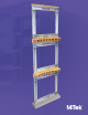
MPF Multi-Lateral Plate Tie
4-1/4"
3"
MP4F
Embossed plate lines
1"
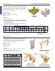
FA3
Typical FA3
one-tab-up installation
Type 1 Type 2
1) Allowable loads have been increased 60% for wind or seismic loads; no further increase
shall be permitted.
2) Refer to drawings for installation type and denition of the various load directions.
3) If installing over plywood, use 8d common nails for 100% of table load.
4) 8d common ( 0.131" dia. x 2-1/2" long) nails may be substituted for 8d x 1-1/2" nails
with no allowable load reduction.
5) NAILS: 8d x 1-1/2 nails are 0.131" dia. x 1-1/2" long.
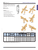
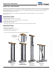
For installation into concrete slabs. The FA3 features a split ange
for nailing to both mudsill and stud for greater framing versatility.
Materials: 16 gauge
Finish: G90 galvanizing
Options: See chart for Corrosion Finish Options
Codes: IBC, FL, LA
Installation:
• Use all specied fasteners. See Product Notes, page 18.
• Use a minimum of two anchors per mudsill. An anchor should
always be within 12" of the end of each mudsill section.
• Do not rely on these anchors to secure concrete sections together between cold joints.
• Insert into wet concrete (minimum strength of 2,500 psi). Place mudsill after concrete cures.
Secure anges to sill (and stud, if applicable), bending anges as needed to achieve a tight t.
Fasten as directed in chart.
• Do not use in red clay brick.
• For installation in severe corrosion environments, see Corrosion Information on pages 11-16.
FA Foundation Anchor
F1
F1
F3
F2
Uplift
4" min.
embed
V
H
Corrosion Finish
Stainless Steel Gold Coat
HDG Triple Zinc
Corrosion Finish Stainless Steel Gold Coat HDG Triple Zinc
Corrosion
Finish
Stainless Steel
Gold Coat
HDG
Triple Zinc
Corrosion Finish
Stainless Steel Gold Coat
HDG Triple Zinc
Corrosion Finish Stainless Steel Gold Coat HDG Triple Zinc
Corrosion
Finish
Stainless Steel
Gold Coat
HDG
Triple Zinc
1-1/2"
4-5/8"
5-3/4"
1"
Typical FA3 standard
installation in concrete