
Use and Care Manual

104
Copyright © 2020 MiTek Industries, Inc. All Rights Reserved
Caps & Bases
Caps & Bases
MiTek
®
Product Catalog
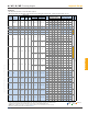
Bearing
1
Uplift
2,8
Ref. No. W1 W2 H
L Beam
100% 160%
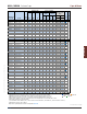
KCC74 CC74 3 6-7/8 3-5/8 8 13 (4) 3/4 (2) 3/4 54845 8155
KCC76 CC76 3 6-7/8 5-1/2 8 13 (4) 3/4 (2) 3/4 54845 8155
KCC77 CC77 3 6-7/8 6-7/8 8 13 (4) 3/4 (2) 3/4 54845 8155
KCC78 CC78 3 6-7/8 7-1/2 8 13 (4) 3/4 (2) 3/4 54845 8155
KCC75X CC71/8-6 3 7-1/8 5-1/2 8 13 (4) 3/4 (2) 3/4 56875 8155
KCC77X CC71/8-71/8 3 7-1/8 7-1/8 8 13 (4) 3/4 (2) 3/4 56875 8155
KCC84 CC84 3 7-1/2 3-5/8 8 13 (4) 3/4 (2) 3/4 60940 8155
KCC86 CC86 3 7-1/2 5-1/2 8 13 (4) 3/4 (2) 3/4 60940 8155
KCC88 CC88 3 7-1/2 7-1/2 8 13 (4) 3/4 (2) 3/4 60940 8155
KCC94 CC94 3 8-7/8 3-5/8 8 13 (4) 3/4 (2) 3/4 71095 8155
KCC96 CC96 3 8-7/8 5-1/2 8 13 (4) 3/4 (2) 3/4 71095 8155
KCC98 CC98 3 8-7/8 7-1/2 8 13 (4) 3/4 (2) 3/4 71095 8155
KCC106 CC106 3 9-5/8 5-1/2 8 13 (4) 3/4 (2) 3/4 77190 8155
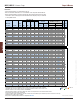
KECC325-4 ECC31/4-4 7 3-1/4 3-5/8 6-1/2 7-1/2 (2) 5/8 (2) 5/8 14650 1750
KECC325-6 ECC31/4-6 7 3-1/4 5-1/2 6-1/2 7-1/2 (2) 5/8 (2) 5/8 14650 1750
KECC44 ECC44 7 3-5/8 3-5/8 4 5-1/2 (1) 5/8 (2) 5/8 12030 1960
KECC45 -- 7 3-5/8 5-3/8 6-1/2 7-1/2 (2) 5/8 (2) 5/8 16405 1960
KECC46 ECC46 7 3-5/8 5-1/2 6-1/2 8-1/2 (2) 5/8 (2) 5/8 18595 1960
KECC47 -- 7 3-5/8 7-1/8 6-1/2 9-1/2 (2) 5/8 (2) 5/8 20780 1960
KECC48 ECC48 7 3-5/8 7-1/2 6-1/2 9-1/2 (2) 5/8 (2) 5/8 20780 1960
KECC525-4 ECC51/4-4 3 5-1/4 3-5/8 8 9-1/2 (2) 3/4 (2) 3/4 30430 6050
KECC525-6 ECC51/4-6 3 5-1/4 5-1/2 8 9-1/2 (2) 3/4 (2) 3/4 30430 6050
KECC525-8 ECC51/4-8 3 5-1/4 7-1/2 8 9-1/2 (2) 3/4 (2) 3/4 30430 6050
KECC57 ECC6-71/8 7 5-3/8 7-1/8 6-1/2 9-1/2 (2) 5/8 (2) 5/8 31170 2105
KECC64 ECC64 7 5-1/2 3-5/8 6-1/2 7-1/2 (2) 5/8 (2) 5/8 25780 2105
KECC66 ECC66 7 5-1/2 5-1/2 6-1/2 7-1/2 (2) 5/8 (2) 5/8 25780 2105
KECC68 ECC68 7 5-1/2 7-1/2 6-1/2 9-1/2 (2) 5/8 (2) 5/8 32655 2105
KECC74 ECC74 3 6-7/8 3-5/8 8 10-1/2 (2) 3/4 (2) 3/4 44295 6050
KECC76 ECC76 3 6-7/8 5-1/2 8 10-1/2 (2) 3/4 (2) 3/4 44295 6050
KECC77 ECC77 3 6-7/8 6-7/8 8 10-1/2 (2) 3/4 (2) 3/4 44295 6050
KECC78 ECC78 3 6-7/8 7-1/2 8 10-1/2 (2) 3/4 (2) 3/4 44295 6050
KECC75X ECC71/8-6 3 7-1/8 5-1/2 8 10-1/2 (2) 3/4 (2) 3/4 45940 6050
KECC77X ECC71/8-71/8 3 7-1/8 7-1/8 8 10-1/2 (2) 3/4 (2) 3/4 45940 6050
KECC84 ECC84 3 7-1/2 3-5/8 8 10-1/2 (2) 3/4 (2) 3/4 49220 6050
KECC86 ECC86 3 7-1/2 5-1/2 8 10-1/2 (2) 3/4 (2) 3/4 49220 6050
KECC88 ECC88 3 7-1/2 7-1/2 8 10-1/2 (2) 3/4 (2) 3/4 49220 6050
KECC94 ECC94 3 8-7/8 3-5/8 8 10-1/2 (2) 3/4 (2) 3/4 57420 6050
KECC96 ECC96 3 8-7/8 5-1/2 8 10-1/2 (2) 3/4 (2) 3/4 57420 6050
KECC98 ECC98 3 8-7/8 7-1/2 8 10-1/2 (2) 3/4 (2) 3/4 57420 6050
KECC106 ECC106 3 9-5/8 5-1/2 8 10-1/2 (2) 3/4 (2) 3/4 62345 6050
1
)
Bearin
g
loads are based on 625
p
si
p
er
p
endicular to
g
rain loadin
g
; no further increase for duration of load is
p
ermitted.
2
)
U
p
lift loads have been increased 60% for wind or seismic loads; no further increase shall be
p
ermitted.
3
)
Allowable loads are based on lumber with a s
p
ecific
g
ravit
y
of 0.50 and a moisture content of 19% or less.
4
)
All bolts shall meet or exceed the s
p
ecifications of ASTM A 307.
5
)
Beams shall be desi
g
ned to su
pp
ort the re
q
uired loads. Beam shear ma
y
limit loads to less than listed loads for device.
6
)
The desi
g
ner shall check
p
ost for re
q
uired loads.
7
)
S
p
liced conditions must be detailed b
y
the s
p
ecifier to transfer tension loads between s
p
liced members b
y
means other than the column ca
p
.
8
)
U
p
lift loads do not a
pp
l
y
to s
p
lice conditions.
New
p
roducts or u
p
dated
p
roduct information are desi
g
nated in blue font.
IBC,
FL,
LA
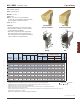
Fastener
Schedule
4
DF/SP
Allowable Loads (Lbs.)
3
Corrosion
Finish
Dimensions (in)
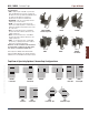
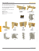
End Column Caps
Center Column Caps
IBC,
FL,
LA
MiTek USP
Stock No.
Steel
Gauge
Column
or Post
Code
Ref.
KCC / KECC Column Caps
Corrosion Finish
Stainless Steel Gold Coat
HDG Triple Zinc
Corrosion Finish Stainless Steel Gold Coat HDG Triple Zinc
Corrosion
Finish
Stainless Steel
Gold Coat
HDG
Triple Zinc
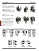
Installation:
• Use all specied fasteners. See Product Notes, page 18.
• Bolt holes should be a minimum of 1/32" to a maximum of 1/16" larger than the bolt diameter.
• Beams shall be designed to support the required loads. Beam shear may limit loads to less than
listed loads for device. A design professional shall determine the adequacy of the post and beam
to resist published loads.
Continued on next page