
Use and Care Manual


280
Copyright © 2020 MiTek Industries, Inc. All Rights Reserved
Plated Truss
Plated Truss
MiTek
®
Product Catalog
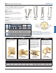
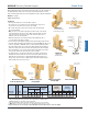
SNP Skewed Nail Plate
The SNP3 Skewed Nail Plate is designed for connecting square
cut corner jack trusses at skews from 0° to 90°, as depicted in
Figure 1 below. An alternate installation for front side attachment
at skews 0° to 45° is depicted in Figure 2 below.
Materials: 16 gauge
Finish: G90 galvanizing
Codes: See chart for code references
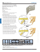
Installation:
• Bend angle only once.
• 8d common (0.131" dia. x 2-1/2" long) nails may be used in lieu
of 8d (0.131") x 1-1/2" nails with no reduction in load.
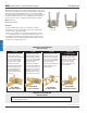
Typical Installation (Figure 1):
• Attach the SNP3 to the supported truss on the acute angle
side so the SNP3 runs behind the end of the jack truss. Use all
the specied fasteners listed in the table below. The fasteners
should be installed nearest to bend line as possible then working
to the opposite end of ange. Not all nail holes will be lled.
• Set the jack truss against the supporting truss and nail the
exposed ange of the SNP3 into place. Use all the specied
fasteners listed in the table below. The fasteners should be
installed nearest to bend line as possible then working to the
opposite end of ange. Not all nail holes will be lled.
Alternate Installation (Figure 2):
• Attach the SNP3 to the supported truss on the obtuse angle
side so the SNP3 is on the front side of the jack truss. Use all
the specied fasteners listed in the table below. The fasteners
should be installed nearest to bend line as possible then working
to the opposite end of ange but no closer than 5/8” from the
end of the truss. Not all nail holes will be lled.
• Set the jack truss against the supporting truss and nail the
exposed ange of the SNP3 into place. Use all the specied
fasteners listed in the table below. The fasteners should be
installed nearest to bend line as possible then working to the
opposite end of ange. Not all nail holes will be lled.
Download Download
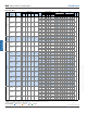
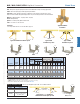
Ref. No. Qty Type Qty Type (100/115/125) (100/115/125)
Figure 1 6 8d x 1-1/2 6 8d x 1-1/2
475 475 415 415
IBC, FL, LA
Figure 2
6 8d x 1-1/2 6 8d x 1-1/2 335 335 295 295 --
1) Allowable loads have been increased 60% for wind or seismic loads; no further increase shall be permitted.
2) Install specified fasteners from the bend line out from each end. Not all nail holes will be filled.
3) When installing SNP3's back to back, the table loads shall be multiplied by a reduction factor of 0.78.
4) Refer to images for installation type.
5)
NAILS:
8d x 1-1/2 nails are 0.131" dia. x 1-1/2" long.
New products or updated product information are designated in
blue font
.
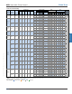
SNP3 TJC37 16
Installation
Type
4
Code
Ref.
Upift
160%
Upift
160%
Fastener Schedule
2
DF/SP
Allowable Loads (Lbs.)
1
S-P-F
Allowable Loads (Lbs.)
1
MiTek USP
Stock No.
Steel
Gauge
Supporting
Member
Supported
Member
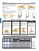
Typical SNP3 installation
Figure 1
SNP3
Alternate SNP3 installation
Figure 2
Supporting
truss
3-1/2"
3-1/2"
Supported
truss
0°
to
90°
Supporting
truss
3-1/2"
3-1/2"
Supported
truss
0° to 45°
3-1/2"
3-1/2"
3-3/8"