
Technical Specifications

56
Holdowns
© 2015 MiTek. All rights reserved.
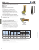
UPHD Holdowns
Engineered for high capacity with minimum deection and low eccentricity.
Materials: See chart
Finish: USP primer
Codes: See page 11 for Code Reference Key Chart
Installation:
• Use all specied fasteners. See Product Notes, page 17.
• Place holdown over anchor bolt and drive screws into post.
• Tighten anchor bolt nuts nger tight snug to base, plus 1/3 to 1/2
additional turns with a wrench. To prevent loosening of the anchor
nut during critical loading, use a locking nut or tighten a second nut
over the rst to lock nuts in place.
• Holdown may be installed off of the plate with no load reduction.
• Post may be shimmed provided the shim acts as a single unit with
the post. Holdown fasteners specied shall not be considered to attach
shim to post. Shim shall be a structural material equal or better than
the post material. Consult a designer or an engineer of record for
appropriate fastening of shim.
Alternate installations:
• Drill hole in concrete or masonry and insert retrot anchor (i.e. epoxy
anchor) capable of resisting uplift and lateral loading.
• Place holdown over anchor bolt and drive screws into post.
• Tighten anchor bolt nuts nger tight snug to base, plus 2-3 additional
turns with a wrench. To prevent loosening of the anchor nut during
critical loading, use a locking nut or tighten a second nut over the
rst to lock nuts in place.
• Post may be shimmed provided the shim acts as a single unit with the
post. Holdown fasteners specied shall not be considered to attach shim
to post. Shim shall be a structural material equal or better than the post
material. Consult a designer or an engineer of record for appropriate
fastening of shim.
Tension
1,5,7
Ref. No. W H D CL Qty 160% 160%
UPHD8 HDQ8-SDS3 10 3-1/4 17-1/4 3-1/8 1-3/8 7/8 24 9165 0.075 7695
UPHD9 HDU11-SDS2.5 10 3-1/4 17-1/4 3-1/2 1-1/2 1 24 11270 0.057 9465
UPHD11 HHDQ11-SDS2.5 7 3 15-1/8 3-1/2 1-1/2 1 24 14395 0.077 12090
UPHD14
HDU14-SDS2.5,
HHDQ14-SDS2.5
7 3 18-3/4 3-1/2 1-1/2 1 30 16695 0.082 14020
1) Allowable loads have been increased 60% for wind and seismic loads; no further increase shall be permitted.
2) The designer must specify anchor bolt type, length, and embedment.
3) Deflections are derived from static, monotonic load tests of devices connected to DF-L wood members with specified fasteners.
4) The designer shall consider the effect of compression, bearing, tension, and combined bending due to device eccentricity when applicable.
5) The UPHD may be elevated off the sill.
6) WS3 wood screws are 1/4 " x 3" and are included with UPHD models.
7) Minimum post thickness is 3" or greater. Consult USP for installations less than 3".
USP
Stock No.
Steel
Gauge
Dimensions (in) Fastener Schedule
Anchor
Bolt
Dia.
2
Code
Ref.
WS3 Wood
Screws
6
30,
F31,
R16
Δ (in)
at 160%
3,5
DF/SP Allowable
Loads (Lbs.)
S-P-F Allowable
Loads (Lbs.)
Tension
1,5,7
Typical UPHD
installation
UPHD
Typical UPHD
concrete
wall installation
W
L
D
CL
Holdowns