
User's Manual


Specifications
Release 3.3 67
ONS Line Specifications
ONS Line Features (ASU)
The ONS line circuit has the following features:
• Maximum of 600-Ohm external loop drive capability. This equates to approximately one
mile of loop range over 26-gauge cable terminated by a 150-Ohm set. Longer loops are
supported but with the characteristics as described by the next bullet item.
14 ONS Tip 14 39 ONS Ring 14
15 ONS Tip 15 40 ONS Ring 15
16 ONS Tip 16 41 ONS Ring 16
17 LS Tip 1 42 LS Ring 1
18 LS Tip 1-1 43 LS Ring 1-1
19 LS Tip 2 44 LS Ring 2
20 LS Tip 1-2 45 LS Ring 1-2
21 LS Tip 3 46 LS Ring 3
22 LS Tip 1-3 47 LS Ring 1-3
23 LS Tip 4 48 LS Ring 4
24 LS Tip 1-4 49 LS Ring 1-4
25 N/C 50 N/C
Music on Hold Connector Pin Allocations (Universal ASU only)
Pin Signal Pin Signal
1 Tip 1 5 Ring 3
2 Ring 1 6 Ring 2
3 Tip 2 7 Tip 4
4 Tip 3 8 Ring 4
Note: The four MOH tips & rings occupy an 8 pin female modular jack located on the rear panel.
Note: Only one port is supported through software on the system.
Paging Connector Pin Assignments (Universal ASU only)
Pin Signal Pin Signal
1 Tip 1 5 Ring 2
2 Ring 1 6 Ring 1-1
3 Tip 1-1 7 Tip 1-2
4 Tip 2 8 Ring 1-2
Note: The paging port employs a single standard 8-pin modular RJ-45 jack located on the rear panel.
Each paging port has a tip/ring pair for audio and a second tip/ring pair designated tip1/ring1 contact
closures for zone control.
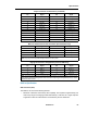
25 pair Connector Pin Allocations (continued)
Pin Signal Pin Signal