MITEL 5000 Communications Platform (CP) IP DECT Stand Configuration and Administration Guide
Part Number 57011426 5000 Communications Platform (CP) IP DECT Stand Configuration and Administration Guide Issue 1.
Notice This guide is released by Mitel Networks Corporation as a guide for certified service personnel. It provides information necessary to properly configure, maintain, and operate the product. The contents of this document reflect current company standards and are subject to revision or change without notice. Some features or applications mentioned may require a future release and are not available in this release. Future product features are subject to availability and cost.
Product Disposal Instructions This symbol indicates that the product is classified as electrical or electronic equipment and should not be disposed of with other commercial or household waste at the end of its working life. For appropriate disposal and recycling instructions, contact your local recycling authority or Inter-Tel provider.
Contents Contents Introduction . . . . . . . . . . . . . . . . . . . . . . . . . . . . . . . . . . . . . . . . . . . . . . . . . . . . . . . . . . . . . . . . . . . . 3 Requirements and Conditions . . . . . . . . . . . . . . . . . . . . . . . . . . . . . . . . . . . . . . . . . . . . . . . . . . . 3 Optional Repeater . . . . . . . . . . . . . . . . . . . . . . . . . . . . . . . . . . . . . . . . . . . . . . . . . . . . . . . . . . . . 3 About the Handset Connection Status Indicators . . . . . . . . . . . .
Contents Network Configuration Notes . . . . . . . . . . . . . . . . . . . . . . . . . . . . . . . . . . . . . . . . . . . . . . . . . . . . 19 IP Configuration . . . . . . . . . . . . . . . . . . . . . . . . . . . . . . . . . . . . . . . . . . . . . . . . . . . . . . . . . . . . 19 File Transfer Protocol . . . . . . . . . . . . . . . . . . . . . . . . . . . . . . . . . . . . . . . . . . . . . . . . . . . . . . . . 19 DHCP . . . . . . . . . . . . . . . . . . . . . . . . . . . . . . . . . . . . . . . . . . .
Introduction Introduction The Mitel 5610 Cordless Handset and IP DECT (Digital Enhanced Cordless Telecommunications) Stand provide basic Mitel 5000 Communications Platform (CP) phone features on a cordless handset. The IP DECT Stand supports up to eight cordless handsets. Each handset is programmed as a separate extension on the 5000 CP. The IP DECT Stand connects to the network through the PC port on a Mitel 5312, 5320, 5324, 5330, 5340, or 5360 IP Phone.
About the Handset Connection Status Indicators To determine if a handset call is being supported by the repeater by using the verification tone: 1. Enable the verification tone feature on the stand. (Refer to the RTX4002 DECT Repeater User Manual for instructions.) By default, this tone is disabled. 2. Initiate a call from the handset in the repeater area when this tone is enabled. If the call is being supported by the repeater, you hear the verification tone (a single tone repeated every 2.5 seconds).
5610 Cordless Handset Feature Set 5610 Cordless Handset Feature Set This section lists the features available for the 5610 Cordless Handset and IP DECT Stand product.
Related Documentation • Quality of service o Type of Service (ToS) • CODECs o G.711 (64 kbps, A-law & u-law) o G.729 • Interoperability o DECT interface (3081) or DECT 6.0 (3080) o WiFi friendly o Maximum Range from stand: 50 m (150 ft) indoors, 300 m (900 ft) outdoor NOTE These features are subject to change without notice.
Registration and Configuration Registration and Configuration After you have physically connected the IP DECT Stand to a Mitel IP Phone, you must program the handsets in the 5000 CP database and register the handsets with the IP DECT Stand.
Register the Handsets with the IP DECT Stand Register the Handsets with the IP DECT Stand To register a handset with the IP DECT Stand (gateway), place the handset in the charging cradle. The first handset automatically registers with the IP DECT Stand after approximately 30 seconds. To register each additional handset on the same IP DECT Stand, you must first reboot the stand by pressing the RESET button on the rear panel of the stand.
Configure all Handsets Using the Configurator Web Interface Configure all Handsets Using the Configurator Web Interface You access the IP DECT Stand Configurator web interface by entering the IP address of the IP DECT Stand into the address field on a web browser (such as Internet Explorer) on a PC connected to the local network. The following procedure covers the minimum configuration required to set up the handsets: 1.
Configure all Handsets Using the Configurator Web Interface 7. Use the menu items in the left frame of the web page to perform the configuration. The following steps provide basic configuration of a handset. See IP DECT Stand Configuration Notes on page 16 for additional details. Figure 2. Example of IP DECT Stand Configurator Web Interface 8. In the left frame of the Configurator web interface, click VoIP Account 1. 9. Enter the following information. Leave the other fields at the defaults. Table 1.
Configure all Handsets Using the Configurator Web Interface Table 1. Handset Settings (Continued) Field Setting Account Mailbox Number Enter the extension number of the voice mail automated attendant. Registrar Enter the IP Address or FQDN of the host 5000 CP. Authentication Username Enter the handset extension number (as programmed on the 5000 CP). DTMF Signaling Set to RFC2833. (Note that the DTMF Encoding Setting in the 5000 CP SIP phone Call Configuration field must also be set to RFC2833.
Configure all Handsets Using the Configurator Web Interface To have calls that are made to each account only ring the associated handset, complete the grid as shown in the following example. In the example below, the grid is configured such that calls to Account 1 ring Handset 1 and Handset 2. Calls to Account 2 ring Handset 2 only, and calls to Account 3 ring Handsets 1 and 3. 13. 14. Page 12 Under Outgoing Identity to be used for, do the following: • Assign an account to each registered handset.
Configure Handset from the Handset Display Menu 15. In the left frame of the Configurator web interface, click Time Settings, and then do the following: • Enter the hostname of a Time Server on the internet, for example: pool.ntp.org • Enter the time server refresh interval, for example: 255 • Set the time difference between Greenwich Mean Time (GMT) and your current location. For example, if you were located in New York, USA, which observes EST you would set the Timezone field to – 5:00 hours.
Configure Handset from the Handset Display Menu 14. Using the handset dial pad, enter the settings listed in the following table. To enter spaces and special characters, press Options and then press Insert symbols. Table 2. Handset Settings Menu Item Setting Display name Enter the user name assigned to this handset. User name Enter the handset extension number (as programmed on the 5000 CP). Note that you need to change the input mode from alphabetical to numeric using the Option softkey.
Change the Handset Display Name and PIN Code Change the Handset Display Name and PIN Code After configuring the handsets, change the default user name and the default PIN code to prevent unauthorized access. Note that the handset PIN code and the Configurator web interface password are independent of each other. If you change the handset PIN code, it does not affect the Configurator web interface password. To change the Display Name: 1.
IP DECT Stand Configuration Notes IP DECT Stand Configuration Notes This section contains configuration notes for the IP DECT Stand Configurator web interface pages and setting. Operation\Home This web page provides IP DECT Stand information, including firmware version, MAC address, IP address, and the registration status of the handsets with the 5000 CP. Setup\VoIP Account You can configure up to eight 5610 handsets by using the VoIP Account numbers one through eight.
Setup\Pincode Settings Setup\Pincode Settings You can set the PINs for accessing the IP DECT Stand (via the handset) and the external TFTP account settings. Table 3. PIN Settings Setting Description VoIP Settings Pincode Enter the PIN code that the user enters on the handset to access system menus (for example, System settings). AC Code Not applicable. HTTP Server Username Enter the user name for the IP DECT Stand Configurator web interface (default is admin).
5610 Handset Configuration Notes 5610 Handset Configuration Notes This section contains configuration notes for the handset display menu settings. The 5610 handset menu provides an interface to the IP DECT Stand to allow the user to control the handset capabilities. From the idle screen, there are three softkey options: • Options • o (selected by pressing the OK key) • Call log Options\Redial This option allows the user to redial the last number dialed.
Network Configuration Notes Network Configuration Notes This section provides network configuration details. IP Configuration You can configure the 5610 Cordless Handset to obtain its IP address via DHCP or to use a static IP address. The IP settings can be changed from the handset menu: Settings – Internet settings, or from the web server IP Settings page.
DHCP DHCP The handsets can be provisioned with an IP address automatically by using DHCP. When configured, the DHCP option 66 returns an IP address or a DNS string of a TFTP server. The handsets use this DHCP feature to retrieve the address of the configuration server. Even though DHCP specifications refer to the TFTP, the handsets use the retrieved address for HTTP as well, if transport is configured for HTTP (HTTP is default method).
SIP Configuration SIP Configuration SIP Server and SIP Accounts The SIP server domain and proxy address can be configured from the handset menu: Settings – VoIP settings – Accounts. Up to eight different servers can be configured individually through the Accounts menu.
SIP Server and SIP Accounts The web server gives access to the following additional settings. Name Values SRV_0_SIP_URI_DOMAIN_CONFIG 0 (default) Description This parameter specifies how a destination URI of the format SIP:@ for an outgoing call must be specified with respect to the part. Possible values are: 0: If application omits the value from the Domain parameter will be added. 1: Application must specify full URI.
SIP Server and SIP Accounts SIP server example setup from configuration file: %SRV_0_SIP_UA_DATA_DOMAIN%:"proxy.goip.dk " %SRV_0_SIP_URI_DOMAIN_CONFIG%:0 %SRV_0_SIP_UA_DATA_SERVER_PORT%:5060 %SRV_0_SIP_UA_DATA_SERVER_TYPE%:0 %SRV_0_SIP_UA_DATA_SERVER_IS_LOCAL%:1 %SRV_0_SIP_UA_DATA_REREG_TIME%:3600 %SRV_0_SIP_UA_DATA_PROXY_ADDR%:"proxy.goip.
STUN, RPORT, SIP Port Settings STUN, RPORT, SIP Port Settings STUN mode, RPORT, RTP port and SIP port can be configured from the web server NAT/RTP Settings page or from the handset menu: Settings – Internet settings – NAT provisioning – Manual.
PIN Protection of Handset Menus Configuration file example: %SIP_STUN_ENABLE%:0 %SIP_RPORT_ENABLE%:1 %NETWORK_STUN_SERVER%:"stun01.sipphone.
Registrations Administration Registrations Administration DECT registrations can be administered by assigning a specific handset to a specific handset ID. This feature is useful when configuration of e.g. call-groups and outgoing line is different for each handset. Use the following parameters. Name Possible values DECT_SUBS_MATCH_IPEI DECT_SUBS_1 … DECT_SUBS_8 0,1 [DISABLE, ENABLE] … Description Registration administration feature. IPEI value for Handset no. 1 … IPEI value for Handset no.
WEB Server Customization Figure 3. LOCAL_HTTP_SERVER_TEMPLATE_TITLE Parameter Controls the Headlines in the Configurator Web Interface LOCAL_HTTP_SERVER_TEMPLATE_TITLE Mitel® 5000 CP IP DECT Stand Configuration and Administration Guide – Issue 1.
Automatic Daylight Saving Time (DST) Adjustment Automatic Daylight Saving Time (DST) Adjustment DST handling can be handled manually or automatically. If manual configuration is chosen the user can change the setting from the handset MMI or it can be set in the configuration files. Automatic handling of DST allows flexible definition of the DST start and end time. Default values enable automatic DST for North America.
Logs Logs The gateway continuously logs information to an internal log buffer. This log can be viewed using the internal web server or the gateway can be configured to automatically upload the log files to the boot server. The configuration parameter VOIP_LOG_AUTO_UPLOAD can be used to control the automatic uploading of log files. Log files are named _(b).log. The first log file is marked with a "b” indicating that it is a boot log. The time in the filename is given in GMT.
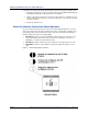
Server Based Configuration Server Based Configuration A configuration file can be retrieved by the handset from a configuration server that is available on the Local Area Network (LAN), as shown in the following figure. Figure 4. Network Topology of a Typical Office Configuration Solution NOTE Optionally security can be ensured by encryption of the configuration file as well as server side authentication by user name and password may be utilized.
Server Based Configuration The product is configured to retrieve a configuration file from a network server using HTTP. Upon agreement with RTX Telecom a series of MAC-addresses will be recognized by the server. The recognized devices will receive a configuration file which redirects the phone to the correct configuration server address. See Figure 5 for a diagram of this process. Figure 5.
Server Based Configuration The following sample configuration file is an example of a fully functional configuration for the 5610 Cordless Handset and IP DECT Stand product: //-----------Network Settings-----------%SIP_RPORT_ENABLE%:1 //A way around NAT %SIP_STUN_ENABLE%:0 //0-disable, 1-enable stun services %NETWORK_STUN_SERVER%:"stun01.sipphone.
Server Based Configuration // ------------- Registration 2 ------------------%SUBSCR_1_SIP_UA_DATA_SIP_NAME%:""//SIP address %SUBSCR_1_SIP_UA_DATA_VOICE_MAILBOX_NUMBER%:""//Mailbox number %SUBSCR_1_UA_DATA_DISP_NAME%:""//Display name for Caller ID %SUBSCR_1_UA_DATA_AUTH_NAME%:""//Auth User ID %SUBSCR_1_UA_DATA_AUTH_PASS%:""//Auth password %SUBSCR_1_SIP_UA_DATA_SIP_NAME_ALIAS%:""//Alias name for Phone UI %SUBSCR_1_SIP_UA_DATA_VOICE_MAILBOX_NAME%:"" // ------------- Registration 3 ------------------%SUBSCR_2
Server Based Configuration // ------------- Registration 7 ------------------%SUBSCR_6_SIP_UA_DATA_SIP_NAME%:""//SIP address %SUBSCR_6_SIP_UA_DATA_VOICE_MAILBOX_NUMBER%:""//Mailbox number %SUBSCR_6_UA_DATA_DISP_NAME%:""//Display name for Caller ID %SUBSCR_6_UA_DATA_AUTH_NAME%:""//Auth User ID %SUBSCR_6_UA_DATA_AUTH_PASS%:""//Auth password %SUBSCR_6_SIP_UA_DATA_SIP_NAME_ALIAS%:""//Alias name for Phone UI %SUBSCR_6_SIP_UA_DATA_VOICE_MAILBOX_NAME%:"" // ------------- Registration 8 ------------------%SUBSCR_7
Feature Support Feature Support This section provides additional information on feature support.
Handset Registration Handset Registration The IP DECT Stand supports the configuration and registration of up to eight handsets. If the handset is configured on the stand, it will repeatedly try and register with the 5000 CP, even if the 5000 CP cannot recognize the DN or password. The handset programming in the stand and the 5000 CP must match to prevent unnecessary traffic flow and constant registration failure scenarios.
Conference Split (End Conference) Conference Split (End Conference) While in a conference, the End Conf softkey is presented. When selected, the user terminates the conference and it is split back into two independent calls. Selecting the conference split will cause the conference to be torn down. One party will be in talk state (active) on the handset, the other will be on hold.
Maintenance Maintenance This section contains information on various types of maintenance that can be performed on the stand and handsets. Firmware Updates Firmware updates are provided via the Mitel Online Software Download site. You download new firmware files from the Mitel Online Software Download site and install them in a location accessible by the 5000 CP TFTP server.
Schedule Automatic Firmware Updates Schedule Automatic Firmware Updates 1. Log into the Mitel IP DECT Stand - Configurator web interface. 2. Click Management Settings. 3. Under Management Settings, set the Management Transfer Protocol field to TFTP. 4. Under Firmware Update Settings, complete the fields as described in the following table. Table 4.
Firmware Update Error Codes Firmware Update Error Codes A number of errors can occur when initiating a firmware update or while a firmware update is in progress. The following list describes all error codes: Code 0: No problems This error code indicates that everything is working as specified. Code 1: Wrong parameter Code1 is an internal error code that indicates that the firmware update application cannot access the selected software version (The selected software is not present in the “dir” list).
Deregistering a Handset Deregistering a Handset Use the following procedure to deregister a handset. To deregister a handset from an IP DECT Stand: 1. From Idle mode, press the OK key, select Settings, and then press the OK key. 2. Select System settings and press the OK key. When prompted for a PIN code, enter the PIN code (default 0000), and then press the OK key. 3. Select Handset settings and press OK. 4. Select Deregister handset and press OK. 5. Deregister Handset? is displayed. Press Yes.
Troubleshooting Troubleshooting DECT registration fails on 2nd handset: Ensure that gateway is opened for registration by pressing the RESET button. Power-cycling will not enable DECT registration due to security. Failed to Register the Handset with Gateway: If you have reset the stand to the defaults (by pressing the RESET button on the rear panel of the stand for greater than 10 seconds) the handset will not register with the stand after you place the handset in the cradle.
Part No. 57011426 Issue 1.