
User Manual

MITSUBISHI
ELECTRIC
9700 SERIES UPS
OWNERS / TECHNICAL MANUAL
Page Number:
3
-
3
MITSUBISHI ELECTRIC 9700 SERIES UPS
(3) CB2 Auxiliary to terminal 55, 56 (300, 375kVA) / 3, 4 (100, 150,
225kVA) in bypass cabinet section.
ii) Power wire Inter-connect
a) Output of transformer cabinet
(1) X1 (A-phase) to A10 bus bar in UPS converter section.
(2) X2 (B-phase) to B10 bus bar in UPS converter section.
(3) X3 (C-phase) to C10 bus bar in UPS converter section.
b) DC Input to UPS
(1) Positive cable to BP bus bar in UPS converter section.
(2) Negative cable to NP bus bar in UPS converter section.
D) Connect the grounding conductor from the input service entrance to the UPS ground
bar.
E) Two (2) sources feeding the UPS
:
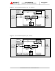
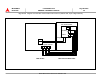
i) Connect the converter input power cables from the input service entrance to the
converter input power terminals identified as A00, B00, C00 or A10, B10, C10 in
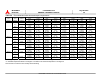
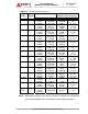
Figures 3.2-a~h. Input cables must be sized for an ampacity larger than the
maximum input drawn by the converter. Refer to Table 3.4 for recommended
cable sizes.
ii) Confirm that an external bypass input circuit breaker (MCCB) is installed (refer to
WARNING 2). Connect the bypass input power cables from the input service
entrance to the bypass input power terminals identified as A40, B40, C40 and N40
in Figures 3.2-a~h. Bypass input cables must be sized for an ampacity larger
than the maximum output current capacity of the UPS. Refer to Table 3.4 for
recommended cable sizes.
F) One (1) source feeding the UPS
:
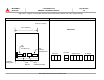
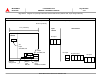
i) Confirm that an external input circuit breaker sized to protect both the converter
input and the bypass lines is installed. Consult equipment nameplate for current
ratings. Connect the bypass input power cables from the input service entrance
to the bypass input power terminals identified as A40, B40, C40 and N40 in
Figures 3.2-a~h. Input cables must be sized for an ampacity larger than the
maximum current capacity of the UPS. Refer to Table 3.4 for recommended
cable sizes.
ii) Using adequately sized conductors per Table 3.4 and referring to the appropriate
figure identified in Figures 3.2-a~h, jumper bypass terminals A40, B40, C40 to
converter input power A00, B00, C00 or A10, B10, C10 identified Figures 3.2-a~h.