
Specifications


4- 8
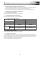
4. REPLACEMENT FROM A-MOTION TO QN-MOTION
(Continued)
Item Q17nCPUN
A17nSHCPUN/A173UHCPU
Points of replacement
A171SH A172SH A173UH
System setting
• Qn(H)CPU will be CPU No.1.
• Use main base units Q33B,
Q35B, Q38B, and Q312B.
• Multiple CPU system is not
supported.
• Main base unit is A17□B.
(A172B, A175B, A178B, A178B-S1,
A178B-S2, and A178B-S3)
Use appropriate units in combination.
Servo system network SSCNET SSCNET Refer to Section 3.1.3.
Teaching unit Usable Usable Use A31TU-D□ series.
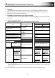
Automatic
refresh
Memory to be
used
Multiple CPU transmission area
in CPU shared memory
SCPU and PCPU share the same
devices.
After the project diversion, manually
assign the devices used by the PLC
CPU to devices in the Motion CPU in
the automatic refresh setting.
Automatic
refresh
setting
For the setting 1 to 4, devices
(D/W/#/M/Y/B) of up to 2k
words can be set per CPU.
LED display Each LED of RUN, ERR Each LED of RUN, ERR -
Latch range
setting
Latch (1)
Range that can be cleared with
the latch clear key
Latch range setting is 1 setting only.
The range is cleared with the L.CLR
switch.
-
Latch (2)
Range that cannot be cleared
with the latch clear key
All clear function
All user data and password
settings are deleted.
None -
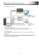
Self diagnosis error
Motion SFC error detection flag
(M2039) turns on when an error
is detected. Self diagnosis error
flag (M9008) and Diagnosis
error flag (M9010) does not turn
on when an error is detected.
When a Motion CPU-specific
error occurs, the error details
are set to D9008.
Even though a PCPU error occurs,
a self diagnosis error will not occur.
Correct the program if necessary.
Motion error detection flag
(M2039)
No matter which error occurs,
M2039 will be ON in Motion
CPU.
-
Depending on the type
of the error that
occurred, M2039 is
turned ON (only when
SFC is used).
Correct the program if necessary.
Latch clear RESET/L.CLR switch
(Note-1)
L.CLR switch -
RUN/STOP RUN/STOP switch RUN/STOP switch -
ROM writing
Execute in the installation/ROM
writing mode.
None -
ROM operation mode
Select with the DIP switch.
None -
Installation mode Select with the DIP switch. -
(Note-1)
: In the multiple CPU system, PLC CPUs/Motion CPUs of No.2 to No.4 cannot be reset individually. The whole multiple CPU system
stops. To reset the whole system, reset the PLC CPU of No.1.