
Specifications


2- 8
2. REPLACEMENT PROPOSAL FROM A-MOTION TO QDS-MOTION
(Continued)
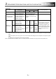
Item Q17nDSCPU
A17nSHCPUN/A173UHCPU
Points of replacement
A171SH A172SH A173UH
Installation mode Select by rotary switch
Select by dip switch -
Mechanical system
program (SV22)
Ball screw and electronic gear
setting of rotary table can be
automatically calculated from the
setting value of "Number of
Pulses/Rev." and "Travel
Value/Rev." of fixed parameter.
Ball screw and electronic gear
setting of rotary table are set
respectively in mechanical system
program.
-
Operation cycle
(default value)
SV13
0.22ms/1 to 4 axes
0.44ms/5 to 10 axes
0.88ms/11 to 24 axes
1.77ms/25 to 32 axes
3.5ms/1 to
4 axes
3.5ms/1 to
8 axes
3.5ms/1 to
20 axes
7.1ms/21
to 32 axes
When the operation cycle is set as
default (automatic), the operation
cycle will change. Operation cycle
changes as left describing, and the
program execution timing will change,
so set the fixed operation cycle if
necessary.
SV22
0.44ms/1 to 6 axes
0.88ms/7 to 16 axes
1.77ms/17 to 32 axes
The operation cycle setting (0.2
[ms]/0.4 [ms]) can be
configured.
(Note-1) (Note-2)
3.5ms/1 to
4 axes
3.5ms/1 to
8 axes
3.5ms/1 to
12 axes
7.1ms/13
to 24 axes
14.2ms/25
to 32 axes
(Note-1): The following restrictions are applied when the communication method is "SSCNET III".
• When the operation cycle is 0.2 [ms], set "0 to 3" for the axis select switch setting of the servo amplifier, and configure the system
setting.
• When the operation cycle is 0.4 [ms], set "0 to 7" for the axis select switch setting of the servo amplifier, and configure the system
setting.
For details, refer to the instruction manual of the servo amplifier.
(Note-2): When MR-J4W3-□B (Software version: A2 or earlier) or MR-J3W-□B is used, set 0.4 [ms] or more for the operation cycle.