AccuSync LCD51VM AccuSync LCD71VM User’s Manual
TO PREVENT FIRE OR SHOCK HAZARDS, DO NOT EXPOSE THIS UNIT TO RAIN OR MOISTURE. ALSO, DO NOT USE THIS UNIT’S POLARIZED PLUG WITH AN EXTENSION CORD RECEPTACLE OR OTHER OUTLETS UNLESS THE PRONGS CAN BE FULLY INSERTED. REFRAIN FROM OPENING THE CABINET AS THERE ARE HIGH VOLTAGE COMPONENTS INSIDE. REFER SERVICING TO QUALIFIED SERVICE PERSONNEL. CAUTION RISK OF ELECTRIC SHOCK • DO NOT OPEN CAUTION: TO REDUCE THE RISK OF ELECTRIC SHOCK, DO NOT REMOVE COVER (OR BACK). NO USER SERVICEABLE PARTS INSIDE.
For the Customer to use in U.S.A. or Canada Canadian Department of Communications Compliance Statement DOC: This Class B digital apparatus meets all requirements of the Canadian Interference-Causing Equipment Regulations. Cet appareil numérique de la classe B respecte toutes les exigences du Règlement sur le matériel brouiller du Canada. C-UL: Bears the C-UL Mark and is in compliance with Canadian Safety Regulations according to CSA C22.2 No. 60950.
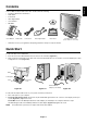
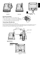
English Contents Your new NEC AccuSync LCD monitor box* should contain the following: • AccuSync LCD monitor with tilt base • Audio Cable • Power Cord • Video Signal Cable • User’s Manual • CD-ROM CD-ROM User’s Manual * Audio Cable Power Cord Video Signal Cable Base Stand AccuSync LCD monitor (base stand not connected) Remember to save your original box and packing material to transport or ship the monitor. Quick Start To attach the Base to the LCD Stand: 1.
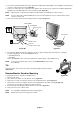
3. Connect the 15-pin mini D-SUB of the video signal cable, Audio Cable and Headphone (not included) to the appropriate connector on the back of the monitor (Figure B.1). 4. Connect one end of the power cord to the monitor and the other end to the power outlet. Place the Video Signal Cable, Headphone (not included) and power cord to the Cable holder (Figure B.1). NOTE: Adjust position of cable that place under the Cable holder to avoid damage for cable or monitor.
English Non-abrasive surface Figure R.1 Figure R.2 Figure R.3 Removing the Base NOTE: Always remove the Base when shipping the LCD. 1. Place monitor face down on a non-abrasive surface (Figure R.1). 2. While using your thumbs, press the bottom tabs upward to unlock. 3. Press the top tabs down to unlock and pull off the stand. Connecting a Flexible Arm This LCD monitor is designed for use with a flexible arm. Please use the attached screws (4pcs) as show in the picture when installing.
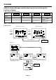
Controls OSM (On-Screen Manager) control buttons on the front of the monitor function as follows: 1. Basic function at pressing each key – SELECT Button + AUTO / RESET At No OSD showing Showing OSM. Shortcut to Bright adjust window. Shortcut to Volume adjust window. At OSD showing Go to Adjustment stage. Cursor goes to left. Cursor goes to right. Go to Icon selection stage. Adjust value decrease or Cursor for adjust goes to left. Adjust value increase or Cursor for adjust goes to right.
Audio volume icon is chosen, depending on the volume condition (AUTO/RESET). BRIGHTNESS Adjusts the overall image and background screen brightness. CONTRAST Adjusts the image brightness in relation to the background. AUTO CONTRAST Adjusts the image displayed for non-standard video inputs. AUTO ADJUST Automatically adjusts the Image Position, the H. Size and Fine setting. LEFT/RIGHT Controls Horizontal Image Position within the display area of the LCD.
OSM LOCK OUT This control completely locks out access to all OSM control functions without Brightness and Contrast. When attempting to activate OSM controls while in the Lock Out mode, a screen will appear indicating the OSM are locked out. To activate the OSM Lock Out function, press “AUTO/ RESET”, then “+” key and hold down simultaneously. To de-activate the OSM Lock Out, press “AUTO/ RESET”, then “+” key and hold down simultaneously.
Safety Precautions and Maintenance • • • • • • • • • FOR OPTIMUM PERFORMANCE, PLEASE NOTE THE FOLLOWING WHEN SETTING UP AND USING THE ACCUSYNC LCD COLOUR MONITOR: DO NOT OPEN THE MONITOR. There are no user serviceable parts inside and opening or removing covers may expose you to dangerous shock hazards or other risks. Refer all servicing to qualified service personnel. Do not spill any liquids into the cabinet or use your monitor near water.
CORRECT PLACEMENT AND ADJUSTMENT OF THE MONITOR CAN REDUCE EYE, SHOULDER AND NECK FATIGUE. CHECK THE FOLLOWING WHEN YOU POSITION THE MONITOR: • • • • • • • For optimum performance, allow 20 minutes for warm-up. Adjust the monitor height so that the top of the screen is at or slightly below eye level. Your eyes should look slightly downward when viewing the middle of the screen. Position your monitor no closer than 40 cm and no further away than 70 cm from your eyes. The optimal distance is 58 cm.
Monitor Specifications AccuSync LCD51VM Monitor LCD Module Diagonal: 38.1 cm/15 inches Viewable Image Size: 38.1 cm/15 inches Native Resolution (Pixel Count): 1024 x 768 Input Signal Active matrix; thin film transistor (TFT) liquid crystal display (LCD); 0.297 mm dot pitch; 250 cd/m2 white luminance, 400/ 450:1 contrast ratio, typical. Video: ANALOG 0.7 Vp-p/75 Ohms Sync: Separate sync.TTL Level (Positive/Negative) Horizontal sync. Positive/Negative Vertical sync.
Specifications LCD71VM Monitor Monitor Specifications AccuSync LCD71VM Monitor LCD Module Diagonal: 43.2 cm/17 inches Viewable Image Size: 43.2 cm/17 inches Native Resolution (Pixel Count): 1280 x 1024 Input Signal Active matrix; thin film transistor (TFT) liquid crystal display (LCD); 0.264 mm dot pitch; 250 cd/m2 white luminance, 450:1 contrast ratio, typical. Video: ANALOG 0.7 Vp-p/75 Ohms Sync: Separate sync.TTL Level (Positive/Negative) Horizontal sync. Positive/Negative Vertical sync.
Reduced Footprint: Provides the ideal solution for environments requiring superior image quality but with size and weight limitations. The small footprint and low weight allow it to be moved or transported easily from one location to another. AccuColor Control Systems: Allows you to adjust the colours on your screen and customize the colour accuracy of your monitor to a variety of standards.
Troubleshooting No picture • The signal cable should be completely connected to the display card/computer. • The display card should be completely seated in its slot. • Check front power Switch and computer power switch should be in the ON position. • Check to make sure that a supported mode has been selected on the display card or system being used. (Please consult display card or system manual to change graphics mode.
Congratulations! You have just purchased a TCO’99 approved and labelled product! Your choice has provided you with a product developed for professional use. Your purchase has also contributed to reducing the burden on the environment and also to the further development of environmentally adapted electronics products. Lead** Lead can be found in picture tubes, display screens, solders and capacitors. Lead damages the nervous system and in higher doses, causes lead poisoning.