Mitsubishi Electric Building Air-conditioner Control System Central Controller G-50A/GB-50A Operation Manual for Initial Setting Web Contents 1 Introduction .........................................................................1 1-1 Conventions Used in This Manual........................................... 1 1-2 Computer Requirements ......................................................... 1 1-3 Notes on using G-50A with the integrated centralized control software (TG-2000A)..........................
1 Introduction A special feature of Mitsubishi Electric Corporation’s “Central Controller G-50A” and "Central Controller GB-50A" are that a PC connected to a LAN can be used to monitor the operation condition of air conditioners, perform air conditioner operations, and make initial settings. This document explains the procedures for making initial settings for the Central Controller G-50A using the web browser.
2 Setting the Operating Environment Given below is an explanation of the PC settings and web browser settings that are required for using a web browser to monitor air conditioner units and perform operations. 2-1 Setting the PC IP Address You need to set an IP address on the PC that will enable you to connect to the G-50A using a web browser. For instance, if the G-50A IP address is [192.168.1.1], the PC IP address will need to belong to the same system (for example [192.168.1.101]).
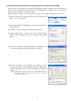
(4) In the [Internet Protocol (TCP/IP) Properties] dialog, click [Use the following IP address] and enter the IP address (for example, “192.168.1.101”) that you want to set in the IP address field. You normally set [255.255.255.0] as the subnet mask. Note: Ask your LAN administrator to provide the IP addresses and subnet mask. (5) Click the [OK] button to close this dialog, and then close the other open dialogs to complete the network setting.
2-2 Setting the Web Browser Perform the necessary web browser settings to enable the web browser to connect to the G-50A. Note: The settings and screen images used as examples in this manual are based on Internet Explorer 6.0. 2-2-1 Not connecting to the Internet If the PC you use for monitoring air conditioners and performing operations is not going to be connected to the Internet, use the procedure given below to set the web browser environment settings.
2-2-3 Connecting to the Internet using a proxy server (Using an existing LAN) If the PC you use for monitoring air conditioners and performing operations is going to access the Internet via proxy server by connecting to an existing LAN such as a LAN within your company, use the procedure given below to set the web browser environment settings. By performing these settings, your PC will connect to a proxy server only when connecting to the Internet.
3 Performing Operations Given below is an explanation of how to connect to the G-50A and how to make various settings for the G-50A. Note: If the G-50A is restarted due to circumstances like a power interruption, wait until the screen on the G-50A main unit displays the normal operation screen (it takes several minutes before the normal operation screen is displayed) before using a web browser to access the G-50A.
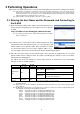
4 Initial Settings 4-1 Setting the Current Date and Time Click [Initial Settings] in the menu, and [Date and Time] screen will appear on the screen. Enter the current date and time, and then press the [Save Settings] button to send the current date and time to G-50A. Note: If the user logs in as a building manager, the operations may be prohibited. Note: If the system is connected to the TG-2000A, make all settings and changes from the TG-2000A so that the data in TG-2000A and G-50A will match.
4-2 Setting the Basic Information and External Input Functions Display the page needed to perform the G-50A basic setting by clicking [Initial Settings]-[Basic System] in the setting menu pane. On this page, you perform the basic setting such as the G-50A unit name, network setting and M-NET setting. Click [Save Settings] to send setting data to the G-50A. After the setting data are sent to the G-50A, a message will appear asking whether or not to restart the G-50A.
4-2-2 M-NET Setting In M-NET Setting, set the G-50A M-NET address, whether or not a K-Control unit is present and which machines send the prohibited controller command. (1) Enter the G-50A M-NET address in the [M-NET Address] field. Normally you should enter [0]. (2) When K-Control air conditioners are connected, click [Used] in the [K-Control Units] field and enter the M-NET address of K transmission converter in the [K Converter Address] field.
4-2-3-1 Settings for when the G-50A is connected to a dedicated LAN (1) Enter the G-50A IP address in the [IP Address] field. If the LAN wiring has been newly set up, allocate IP addresses to the G-50A units in a sequential order starting with [192.168.1.1]. For example the first G-50A unit will receive an IP address of [192.168.1.1], the second G-50A unit will receive an IP address of [192.168.1.2] and so on.
4-2-3-2 Settings for when the G-50A is connected to an existing LAN When connecting the G-50A to an existing LAN, consult with the network administrator who is responsible for the LAN before setting the IP address, subnet mask, or gateway address. [Example of a Permanent LAN System] Backbone LAN Gateway IP: 10.130.1.250 Gateway IP: 10.130.2.250 Receive from the LAN administrator. G-50A IP Address Subnet Mask G/W Address Receive from the LAN administrator. Web Monitor PC Web Monitor PC :10.130.1.
(4) Selecting [ON/OFF/Prohibit/Permit (Pulse signal)] makes it possible to use pulse signals to run multiple units, stop multiple units, prohibit local operation and permit local operation. In this mode, it is possible to freely operate the remote control except during the pulse signal input. 1 2 3 4 5 6 7 8 9 Run Stop Prohibit Permit DC12V :Pulse generator Connection to G-50A (CN2) 0.5 - 1.0 Seconds Contact ON Run Contact OFF Contact ON Stop Contact OFF Run Stop 0.5 - 1.
4-3 Group Setting Display the page needed to register the group of air conditioners to be connected to the G-50A and to set the group name by clicking [Initial Settings]-[Groups]. On this page, you perform the basic setting such as the G-50A unit name, network setting and M-NET setting. Click [Set to G-50A] to send setting data to the G-50A. Note: If the user logs in as a building manager, some of the operations may be prohibited.
(2) To register remote controllers in a group, click on the [Remote Controller Registration] field to display the [Select Unit Addresses] screen, and click on the numbers corresponding to the units to be registered. The ones that are selected will be shown with a yellow-green background. To cancel the selection, click on them again. Deselected items will be shown with a gray background. Note: A maximum of 2 remote controls can be registered in one group.
4-4 Interlocked Setting To interlock the operation of LOSSNAY with the run/stop status of the indoor units, click on [Initial Settings]-[Interlocked LOSSNAY] in the menu to bring up the Interlocked LOSSNAY screen, and enter the interlock conditions. Click [Save Settings] to send setting data to the G-50A. Note: If the user logs in as a building manager, the operations may be prohibited.
4-5 Block Setting By performing block settings, multiples of air conditioner groups can be collectively monitored or operated from the Web or TG-2000A. It also enables energy-save/peak cut controls. Bring up the Block Setting screen by clicking [Initial Settings]-[Blocks] in the menu, and register the groups in the block to utilize these features. Click [Save Settings] to send setting data to the G-50A. Note: If the user logs in as a building manager, some of the operations may be prohibited.
5 Functions 1 5-1 Error mail reports/E-mail communication Click on [Functions 1] – [E-Mail] in the menu to open the [E-mail] window and make necessary settings to perform remote monitoring via mail, using error mail report or the maintenance tool. Click [Save Settings] to send setting data to the G-50A. Note: The use of the error mail report function requires a separate license registration. Confirm on the license registration screen (Ch8) that the license registration has been completed.
5-1-2 Setting the Mail Server Information Enter the mail server information provided by either the ISP or the LAN administrator. Either the IP address or the host name (server name) can be entered in the mail server field. Make necessary settings depending on the functions to be used, using the table below as a reference.
(4) To e-mail an error when an error occurs on general equipment connected to PLC for general equipment, click the PLC Connection button, which appears at the time of selection of "General Equipment", to set the IP address of PLC for general equipment. The row number of the set IP address will be in an error mail as a PLC number. (Eg. When an error occurs on the No.
5-2 Energy-Save Control and Peak Cut Control Click on [Functions 1] – [Peak Cut] in the menu to bring up the peak cut control screen, and make necessary peak cut settings to use the energy-save or peak cut control function. Click [Save Settings] to send setting data to the G-50A. Note: The use of energy-save/peak cut control functions requires a separate license registration. Confirm on the license registration screen (Ch8) that the license registration has been completed.
5-2-1 Initialization of the PLC (When the PLC is in use) Before using the PLC Software for demand input or Electric Amount Count Software, click on the PLC initialize button once to initialize the internal memory. Note: Do not initialize the memory after the operation has begun, for it will clear all operation data. 5-2-2 Setting the PLC software for demand input (demand input method) (1) Enter the IP address for the PLC software for demand input.
5-2-6 Setting the Outdoor Unit Control Method (All methods) Make the energy-save control setting for the outdoor units for each energy-save level. Note: M-NET addresses are displayed on outdoor units of City multi type. M-NET addresses and group names are displayed on A-control units (Slim units). Note: As for A-control outdoor units, only the inverter models can be put on the energy save control. Do not make the energy save settings for the constant speed models. Copy Paste Click to copy the settings.
5-2-7 Setting the Indoor Unit Control Method (All methods) Make the energy-save control settings for the outdoor units for each energy-save level. The settings are made for each operation block. If the operation blocks have not been set up, refer to section 4-5 on how to set the operation blocks. Copy Paste Click to copy the settings. Click to paste the settings. Control Level Batch Operations Used to make settings for all outdoor units at once.
6 Functions 2 6-1 Limiting the Set Temperature Operating Range Click on [Function2]-[Set Temperature Range Limit] in the menu to open the set temperature range limit screen, and make necessary settings to limit the set temperature operating range of the local remote controller. Each user operation will be limited by setting the lower limit and the upper limit of the set temperature for cooling operation, which leads to energy saving.
6-2 Night Mode Schedule Click on [Function2]-[Night Mode Schedule] in the menu to open the night mode schedule screen and make necessary settings to switch the outdoor unit operation mode to the night mode (low-noise operation), and set the night mode time interval. Use this mode when low-noise operation of the outdoor unit is preferable during night. Note: Make this setting only when all the units operate normally.
6-3 Auto-Changeover of Y series Click on [Function2]-[Auto-changeover] in the menu to open the auto-changeover screen and make necessary settings to switch the operation mode between cooling and heating automatically of the indoor units connected to the same outdoor unit. Set the change over mode and the target units.
7 User Setting Click on [User settings] in the menu to open the user setting screen and make necessary user settings to limit available functions of a building manager and to change user names and passwords of maintenance user and building manager. A building manager must change group names when a tenant has been changed. However, for basic setting information, such as connection information of air conditioners, that one doesn’t want to be changed, please make this user setting.
Table 7-1 Available Function List Function Content Date and time Basic system Current date and time setting *1 G-50A network setting, external output setting Group name Groups Group structure Initial setting *1 *1 Interlocked LOSSNAY Blocks E-Mail Block name Block structure Block name setting *1 *1 Functions1 Peak cut Control method System structure Functions2 Group name setting Connection setting of indoor units, remote controllers and system controllers in a group Connection setting of i
8 Registering a License for Optional Function Given below is an explanation on how to register a license for optional functions. In the Login screen (see3-1), click [License registration for optional functions] and the License Registration of Optional Functions screen will appear. Please ask the dealer you purchased the product from for more details on the optional functions and how to purchase a license number. Sub menu Click to return the Login page.
HEAD OFFICE: MITSUBISHI DENKI BLDG.