
Instruction manual


ENGLISH
13
•••••••••••••••••••••••••••••••••••••••••••••••••••••••••••••••••••••••••••••••••••••••••••••••••••••••••••••••••••••••••••••••
Beginning
VIDEO
1
MAIN
OFF
ON
AC IN
~
234 56789
1
4
RESET
RS-232C
23 56789
1
ALARM IN
2
3
4
5
6
7
8
9
CLOCK ADJ
REC
EMERGENCY
MODE OUT 1
MODE OUT 2
MODE OUT 3
MODE OUT 4
MODE OUT 5
CALL OUT
CALL OUT GND
MAX 350mA
DC 12V OUT
GND
CAMERA OUT
RS-232C
RESET
CAMERA IN
INOUT
OUTPUT A
OUTPUT B
MIC
GND
AUDIO
100-240V
Y/C
ETHERNET
RECEIVE
SEND
12 13
11
109
876
5
1
23 4
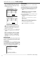
This unit must be earthed at all times. Never con-
nect this unit to a power outlet which does not have
an earth terminal.
Please use the AC power cord accessory.
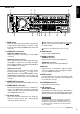
6. GND terminals
It is the common GND terminal.
7. AUDIO connectors
AUDIO IN connector
Input connector for audio signal (RCA pin).
AUDIO OUT connector
Output connector for audio signal (RCA pin).
8. MIC jack
Input connector for microphone (600 ohm imped-
ance). Use of MIC for audio recording has priority to
use of the AUDIO IN connector.
9. RESET button
Pressing this button resets the unit and the power
turns off. In this case, video data, menu settings and
the current time are kept.
10. ALARM IN terminals
Input terminal for alarm signal.
11. I/O terminals
CLOCK ADJ terminal
Input terminal to set the present time. Time display is
adjusted to the nearest hour (00 minutes 00 seconds)
when this terminal receives the CLOCK ADJ signal.
INFORMATION
The on-screen clock can be reset to the nearest hour,
by applying a signal to the CLOCK ADJ terminal. For
example, if the current time is 11:29:59, it will be reset
to 11:00:00, and if the current time is 11:30:00, it will be
reset to 12:00:00.
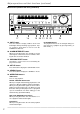
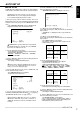
1. MAIN switch
This is the main power switch. When using this unit,
set this switch to ON. Otherwise, the power cannot
be turned on/off using the POWER button on the front
of the unit.
2. VIDEO OUT connectors
OUTPUT A VIDEO connector
Output connector for video signal to monitor (BNC
connector).
OUTPUT A S(Y/C) connector
This is output connector for video signals that sepa-
rate brightness signals and color signals for higher
picture quality. Simultaneous output along with OUT-
PUT A VIDEO is also possible.
OUTPUT B connector
Output connector for video signal to monitor only for
live image (BNC connector)( see page 37). To
display the image, set “OUTPUT B ON/OFF” on the
<MPX DISPLAY SETTINGS> screen to “ON”. The
playback image cannot be put out to the OUTPUT B
connector.
3. CAMERA IN connectors
Input connector for signal of camera (BNC connector).
4. CAMERA OUT connectors
Camera video output connectors for use of BNC con-
nectors. If the MAIN switch is ON, the loop through
output is possible for the camera image inputted into
each CAMERA IN connector.
5. AC power socket
This socket connects to the power cord. Earth ter-
minal is for safety. Use the 100 ~ 240V plug with
earth for the power of this unit.
■ Rear View