ENGLISH HDD Extension Unit DEUTSCH INSTALLATION AND OPERATION MANUAL MODEL NEDERLANDS ITALIANO ESPAÑOL FRANÇAIS DX-ZD5UE(Z) THIS INSTRUCTION MANUAL IS IMPORTANT TO YOU. PLEASE READ IT BEFORE USING YOUR HDD EXTENSION UNIT.
WARNING RISK OF ELECTRIC SHOCK DO NOT OPEN WARNING: TO REDUCE THE RISK OF ELECTRIC SHOCK, DO NOT REMOVE COVER (OR BACK) NO USER-SERVICEABLE PARTS INSIDE REFER SERVICING TO QUALIFIED SERVICE PERSONNEL. The lightning flash with arrowhead symbol, within an equilateral triangle, is intended to alert the user to the presence of uninsulated “dangerous voltage” within the product’s enclosure that may be of sufficient magnitude to constitute a risk of electric shock.
ENGLISH AVERTISSEMENT DANGER D’ÉLECTROCUTION NE PAS OUVRIR AVERTISSEMENT: POUR ÉLIMINER TOUT RISQUE D’ÉLECTROCUTION, NE PAS OUVRIR LE COUVERCLE (OU LA PARTIE ARRIÈRE). AUCUNE PIECE RÉPARABLE PAR L’UTILISATEUR NE SE TROUVE À L’INTÉRIEUR. POUR TOUTE INTERVENTION D’ENTRETIEN OU DE RÉPARATION SE CONFIER AUX TECHNICIENS QUALIFIÉS.
Important safeguards PLEASE READ ALL THESE INSTRUCTIONS REGARDING YOUR HDD EXTENSION UNIT AND RETAIN FOR FUTURE REFERENCE. FOLLOW ALL WARNINGS AND INSTRUCTIONS MARKED ON THE HDD EXTENSION UNIT. 1. Read Instructions All the safety and operating instructions should be read before the appliance is operated. 2. Retain Instructions The safety and operating instructions should be retained for future reference. 3. Heed Warnings All warnings on the appliance and in the operating instructions should be adhered to.
17.Damage requiring Service Unplug this product from the wall outlet and refer servicing to qualified service personnel under the following conditions: (a) When the power-supply cord or plug is damaged. (b) If liquid has been spilled, or objects have fallen into the product. (c) If the product has been exposed to rain or water. (d) If the product does not operate normally by following the operating instructions.
Caution and care HEAVY OBJECTS SHOULD NEVER BE PLACED ON THE UNIT (E.G., MONITOR) NEVER TOUCH OR INSERT ANY OBJECT INSIDE THE UNIT Touching the inside of the cabinet or inserting foreign objects of any kind through the ventilation holes not only creates a safety hazard but can also cause extensive damage. PROTECT THE POWER CORD Damage to the power cord may cause fire or shock hazard. If the mains cord is damaged, turn OFF the MAIN switch and carefully unplug the cord by holding the mains plug.
ENGLISH WARNING: The power cords for use in the U.S., the continent of Europe, and U.K. are included with this unit. Use the appropriate one for your country. The power cord for use in the U.S. is used for 120V only. Never connect to any outlet or power suply having a different voltage or frequency. Before starting recording important images, make sure to perform trial recording to ensure that images are properly recorded. The user will not be indemnified for problems (e.g.
Contents Important safeguards .................................................... i-iv Caution and care ............................................................ 2-3 Contents ............................................................................. 4 Major operations and their functions ........................... 5-6 Front view ................................................................ 5 Rear view ................................................................. 6 Connections ................
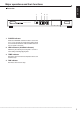
Major operations and their functions 2 1 POWER HDD EXTENSION UNIT DX-ZD5 HDD 1 HDD 2 ENGLISH Front view 3 4 TEMP FAN ACCESS 1. POWER indicator When the EXTERNAL CONTROL switch is set to OFF, or it is set to ON with the connected recorder turned on, this indicator illuminates while the MAIN switch on the rear panel is turned on. 2. HDD indicators (ACCESS indicators) Momentary flash during accessing HDD 1 or HDD 2. Flash during recording/copying data. 3.
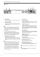
Major operations and their functions Rear view 3 EXTERNAL CONTROL ON OFF MAIN OFF ON 4 5 TEMP ALM FAN ALM 2 CONT IN CONT OUT CONT OUT 1 ~ AC IN 100-240V 1. MAIN switch This is the main power switch. When using this unit, set this switch to ON. 2. AC power socket Used to connect the power cord. Earth terminal is used for safety. Use the 100 to 240 V plug with earth for the power of this unit.
Connections ENGLISH 1. Connectable recorders MITSUBISHI DIGITAL RECORDER DX-TL5000U, DX-TL5000E 2. Connection example • Connect this unit and a digital recorder by using the supplied USB cable. • It is possible to connect some DX-ZD5UE(Z), as shown below.
Connections 3. Startup step1. Turn on the power of this unit. step2. Turn on the main switch of the recorder. The POWER indicator of this unit illuminates. step3. After “POWER OFF” is displayed on the LCD of the recorder, press the POWER button of the recorder. step4. The indicators of HDD 1 and HDD 2 momentary flash in green. When the power of the recorder is turned on, the connection is completed. 4. Setting This unit can be used as a main device or copy device.
User Menu 2 Copy step 4 step 3 steps 1, 2 1 Copy Data to Copy 1 Drive 1 + 2 Range of Copy 3 Set Copy 1 Drive step1. Set the camera number to be copied. • The button function changes between “All Off” and “All On” each time you select this button. You can switch on and off for all the cameras easily by using this button. • The picture is not copied when there is no recorded picture of the set camera number or time. step2. This item is used to copy the data by specifying only the start point.
Connections • “LPA” appears for “From Main” when “Long Pre-Alarm Area” (System Menu Memory Data Management Setting for Main Memory Change Partition Setting) is set to other than “0 %” in the recorder. • Make sure that the MAIN switch on the rear panel is turned OFF when attaching or removing the HDD. Wait at least 1 minute after turning off the power. When a recorder is connected, turn off the recorder, too. step3. • Do not remove the top cover of the unit.
Remove the screws. step7. Attach the new HDD onto the HDD tray with four screws. ENGLISH step2. • Make sure to attach the HDD in the correct direction. • When attaching the HDD to this unit, use the supplied screws. step3. Remove the front covers. • Remove the cover on the right side first. • Then, push the left side cover to the right to remove. step4. step5. step8. Insert the hard disk tray halfway. step9. Connect the cords. step10. Insert the hard disk tray completely.
Connections step11. Attach the metal part. step15. Fix the front covers with two screws. step16. Close the left end of each screw covers on both sides of the cover. • Adjust the upper side first, then push the lower side into the unit. • Take care not to deform the springs. step12. Fix the metal part with four screws. step13. Connect the cord to the circuit board on the metal part. step14. Attach the front covers.
ENGLISH 6. Troubleshooting If problems with the unit persist even after you’ve followed the suggestions below, please disconnect the power cord and contact the retailer from whom you purchased the unit. Description of problem The unit is not turned on. This unit does not work correctly. TEMP indicator illuminates. FAN indicator illuminates.
Recording time table Continuous recording time table HDD continuous recording time Displays the estimated recordable time (when recording on two 250 GB HDDs). • The following table shows the total number of recordable frames of all the cameras which are set for recording. • When recording data in NTSC system • Without audio recording d : day, h : hour Number of frames /sec.
ENGLISH • With audio recording
Recording time table • When recording data in PAL system • Without audio recording d : day, h : hour Picture Number of frames /sec. grade 200 100 66.7 50 40 33.
ENGLISH • With audio recording
Specifications General Rated Power Supply: Rated Input: Operating Temperature: Relative Humidity: Altitude: Dimensions: Weight: 100 to 240 V AC ±10 %, 50/60 Hz 0.7 - 0.4 A (100-240 V) 41 °F-104 °F (5 °C to 40 °C) Max. 80 (%) Max.
MITSUBISHI DIGITAL ELECTRONICS AMERICA, INC. 9351 Jeronimo Road, Irvine, CA 92618, U.S.A. Phone 949-465-6000 www.mitsubishi-imaging.com Tech Support 888-307-0309 tsupport@mdea.mea.com UK Mitsubishi Electric Europe B.V. UK Branch Office Visual Information Systems Division Travellers Lane Hatfield Herts AL10 8XB Telephone: +44 (1707)-278 684 Fax: +44 (1707)-278 541 GERMANY Mitsubishi Electric Europe B.V. German Branch Office Electric Visual Systems Gothaer Str.