
Service manual

1
2
3
4
5
6
7
8
9
10
11
12
13
14
1
2
3
4
5
6
7
8
9
10
11
12
13
14
2
2
1
3
5
7
X1
X2
X3
X4
X5A
X12
X11
X6
X8
X7
TBO.2
5
3
1
F1
F2
CN01
(BLK)
Signal
output
(Error)
Signal
output
(Defrost)
Signal
output
(Booster
heater2+)
MXV
M
1
~
M
1
~
MP2
M
1
~
MP3
MP1
M
1
~
2WV2
M
1
~
1
3
CNP1
(WHT)
1
3
1
3
Signal
output
(Boiler)
1
3
CNPWM
(WHT)
CNIH
(ORN)
2
1
3
CNBHT(BLK)
X5B
X10
CNBC
(GRY)
CNBH
(WHT)
TBO.1
X9
X13
Open
Close
N
3
Signal
output
(Immersion
heater)
2
22
ECB1
L
(1)
N
(3)
BHCP
BLU
BLU
RED
WHT/No.2
WHT/No.1
RED
VLT
VLT
GRY
GRY
BHC1
BHT
642
531
A1
A2
BH1
BHF
2
4
Power supply
to Booster heater
~/N 230V 50Hz
642
531
A1
A2
*
1
91011
3WV
M
1
~
*
1
TBO.1
91011
2WV1
M
1
~
TBO.1
3WV 2WV1
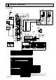
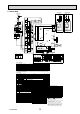
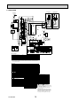
Table 1 Signal Inputs
Name
Terminal block Connector
Item OFF (Open) ON (Short)
IN1 TBI.1 1-2
— Room thermostat 1 input
Refer to SW2-1 in <6-11 Dip switch setting>
IN2 TBI.1 3-4 CN2F
Flow switch 1 input
Refer to SW2-2 in <6-11 Dip switch setting>
IN3 TBI.1 5-6
— Flow switch 2 input (Zone1)
Refer to SW3-2 in <6-11 Dip switch setting>
IN4 TBI.1 7-8
— Demand control input
Normal
Heat source OFF/Boiler operation *2
IN5 TBI.1 9-10
— Outdoor thermostat input *1
Standard operation
Heater operation/Boiler operation *2
IN6 TBI.1 11-12
— Room thermostat 2 input
Refer to SW3-1 in <6-11 Dip switch setting>
IN7 TBI.1 13-14
— Flow switch 3 input (Zone2)
Refer to SW3-3 in <6-11 Dip switch setting>
*1. If using outdoor thermostat for controlling operation of heaters, the lifetime of the heaters and
related parts may be reduced.
*2. To turn on the boiler operation, use the main controller to select “Boiler” in “External/input setting“
screen in the service menu.
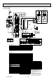
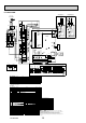
Symbol Name Symbol Name
TB1
Terminal block <Power supply, Outdoor unit>
TH1 Thermistor (Room temp.)(Option)
ECB1
Earth leakage circuit breaker for booster heater
THW1 Thermistor (Flow water temp.)
MP1
Water circulation pump1(Space heating & DHW)
THW2 Thermistor (Return water temp.)
MP2 Water circulation pump2
(Space heating for Zone1)(Field supply)
THW5 Thermistor (DHW tank water temp.)(Option)
THW6 Thermistor (Zone1 flow temp.)(Option)
MP3 Water circulation pump3
(Space heating for Zone2)(Field supply)
THW7 Thermistor (Zone1 return temp.)(Option)
THW8 Thermistor (Zone2 flow temp.)(Option)
3WV(2WV1)
3-way valve (2-way valve1)(Field supply) THW9 Thermistor (Zone2 return temp.)(Option)
2WV2 2-way valve2 (Field supply)
THWB1
Thermistor (Boiler flow temp.)(Option)
MXV Mixing valve (Field supply)
THWB2
Thermistor (Boiler return temp.)(Option)
BHT Thermostat for booster heater IN1 Room thermostat 1 (Field supply)
BHF Thermal fuse for booster heater IN2 Flow switch 1
BH1 Booster heater 1 IN3 Flow switch 2 (Field supply)
BHC1 Contactor for booster heater 1 IN4 Demand control (Field supply)
BHCP Contactor for booster heater protection IN5 Outdoor thermostat (Field supply)
IN6 Room thermostat 2 (Field supply)
IN7 Flow switch 3 (Field supply)
FLOW TEMP. CONTROLLER (FTC4)
TBO.1~2
Terminal block <Outputs>
TBI.1~2
Terminal block <Signal Inputs, Thermistor>
F1~F2
Fuse (T6.3AL250V)
SW1~4
Dip switch *See 6-11 Dip switch setting
X1~X12
Relay
LED1 Power supply (FTC4)
LED2 Power supply (Main controller)
LED3 Communication (FTC4-Outdoor unit)
LED4 Reading or writing data to SD card
CNPWM
Pump speed control signal for MP1
CN108
SD card connector
NL
S3S2S1
NL
S3S2S1
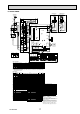
Figure 1
To outdoor
unit
TB1
ORN
ORN
YLW
BLK
BLK
YLW
GRN/YLW
To outdoor
unit
Power supply
~/N 230V 50Hz
TB1
ORN
BLU
RED
BLU
RED
YLW
GRN/YLW
1
3
CN3C
(BLU)
5
3
1
1
3
5
3
1
CN01
(BLK)
ORN
BRN
CN3C
(BLU)
CN01
(BLK)
ORN
ORN
BRN
YLW
Cylinder unit powered
by independent source.
Cylinder unit powered
via outdoor unit
CIRCUIT
BREAKER
TBO.1
3
9
5
1
7
2
8
4
6
11
10
12
13
14
TBO.2
FTC4
3
9
5
1
7
2
8
4
6
11
10
12
13
14
TBI.1
12610
14
8
137119
4
53
2
1
TBI.2
12
6
10 148
13
7
11
9
4
5
3
2
1
13
CNP1(WHT)
1
5
CNV1
(WHT)
1
3
CN3C
(BLU)
5
3
1
CN01
(BLK)
18
SW3
18
SW1
LED1
LED3
1
1
8
6
SW2
SW4
TBI.1
1310 12 1411746593281
TBI.2
13
10
12
14
11
7
46
59
3
2
81
1
2
CN20
(RED)
TH1
1
4
THW1
1
2
1
3
IN2
IN7
IN6
IN5
IN4
IN3
IN1
t
°
t
°
THWB2
THWB1
THW8
t
°
THW6
t
°
THW7
t
°
THW9
t
°
Main
controller
1 2
THW2
THW5
CNW5
(WHT)
CNW12
(RED)
t
°
t
°
t
°
t
°
1
3
1
4
CN2F
(YLW)
CN20
(RED)
CN21
(YLW)
CNW12
(RED)
CNW5
(WHT)
1
2
1
2
CN108
1
3
13
13
CNBH
(WHT)
CNBHT
(BLK)
13
CNIH
(ORN)
CNBC
(GRY)
1
7
LED4
LED2
1
2
CN22
(BLU)
CNPWM
(WHT)
1
3
5
1
Wireless receiver
(Option)
CNRF
(WHT)
5
1
CN105
(RED)
CN2F
(YLW)
CN22
(BLU)
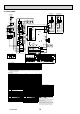
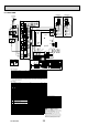
Table 2 Outputs
Name
Terminal block Connector
Item OFF ON
OUT1
TBO.1 3-4
CNP1
Water circulation pump 1 output (Space heating & DHW) OFF ON
OUT2
TBO.1 5-6
—
Water circulation pump 2 output (Space heating for Zone1) OFF ON
OUT3
TBO.1 7-8
—
Water circulation pump 3 output (Space heating for Zone2) OFF ON
OUT4
TBO.1 9-11
CNV1
3-way valve (2-way valve1) output Heating DHW
OUT5
TBO.1 12-13
—
Mixing valve output
Stop Close
TBO.1 13-14 Stop Open
OUT6
—
CNBH 1-3
Booster heater 1 output OFF ON
OUT7
—
CNBH 5-7
Booster heater 2 output OFF ON
OUT8
TBO.2 11-12
—
Booster heater 2+ output OFF ON
OUT9
TBO.2 9-10
CNIH
Immersion heater output OFF ON
OUT10
TBO.1 1-2
—
Boiler output OFF ON
OUT11
TBO.2 1-2
—
Error output Normal Error
OUT12
TBO.2 3-4
—
Defrost output Normal Defrost
OUT13
TBO.2 7-8
—
2-way valve 2 output DHW Heating
1. Symbols used in wiring diagram are,
: connector, : terminal block.
2. Indoor unit and outdoor unit connecting wires
have polarities, make sure to match terminal numbers
(S1, S2, S3) for correct wirings,
3. Since the outdoor unit side electric wiring may change,
be sure to check the outdoor unit electric wiring
diagram for servicing.
4. This diagram shows the wiring of indoor unit and
outdoor unit connecting wires (specification of 230V),
adopting superimposed system of power and signal.
When work to supply power separately to indoor
unit and outdoor unit was applied, refer to Figure 1.
19
6-7. EHPX-VM2B
OCH532A