
Service manual


23
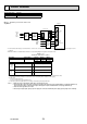
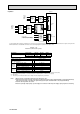
Automatic switch to heat source only operation
Back-up heat source operation (*1) will automatically run when the outdoor unit stops abnormally.
To enable the function, switch Dip SW 2-5 to ON.
During the back-up operation, an error code(s) and the contact number will be displayed alternately.
External output (OUT11) will be available.
To clear the fault(s), reset the power breakers on the indoor and outdoor units.
<Applicable error codes (*2)>
E6 to E9, ED, P6, P8, U1 to U8, UD, UE, UF, UL, UP
(*1) Prolonged running of the back-up operation may affect the life of the heat source.
(*2) For safety reasons, this function is not available for certain faults. (System operation must be stopped and only pump keeps running.)
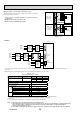
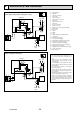
6-11. Dip switch setting
Located on the FTC4 printed circuit board are 4 sets of small white switches
known as Dip switches. The Dip switch number is printed on the circuit board
next to the relevant switches. The word ON is printed on the circuit board and on
the Dip switch block itself. To move the switch you will need to use a pin or the
corner of a thin metal ruler or similar.
Dip switch settings are listed in the table below.
Before changing any switch settings, ensure power supplies to indoor and out-
door units are isolated/powered off.
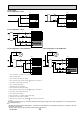
Dip switch Function OFF ON
Default settings:
Indoor unit model
SW1
SW1-1 Boiler WITHOUT Boiler WITH Boiler OFF
SW1-2 Heat pump maximum outlet water temperature 55ºC 60ºC ON *1
SW1-3 DHW tank WITHOUT DHW tank WITH DHW tank OFF
SW1-4 Immersion heater WITHOUT Immersion heater WITH Immersion heater OFF
SW1-5 Booster heater WITHOUT Booster heater WITH Booster heater ON
SW1-6 Booster heater function For heating only For heating and DHW ON
SW1-7 Outdoor unit type Split type Packaged type
OFF: E*SC-*M*B
ON : EHPX-*M*B
SW1-8 Wireless remote controller WITHOUT Wireless remote controller WITH Wireless remote controller OFF
SW2
SW2-1 Room thermostat1 input (IN1) logic change
Zone1 operation stop at thermostat short Zone1 operation stop at thermostat open
OFF
SW2-2 Flow switch1 input (IN2) logic change Failure detection at short Failure detection at open ON
SW2-3 Booster heater capacity restriction Inactive Active
OFF: Except
E***-VM2B
ON : E***-VM2B
SW2-4 Cooling mode function Inactive Active
OFF: Except
ERSC-VM2B
ON : ERSC-VM2B
SW2-5
Automatic switch to backup heat source operation
(When outdoor unit stops by error)
Inactive Active *2 OFF
SW2-6 Mixing tank WITHOUT Mixing tank WITH Mixing tank OFF
SW2-7 2-zone temperature control Inactive Active OFF
SW2-8 — — - OFF
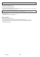
SW3
SW3-1 Room thermostat 2 input (IN6) logic change
Zone2 operation stop at thermostat short Zone2 operation stop at thermostat open
OFF
SW3-2 Flow switch 2 input (IN3) logic change Failure detection at short Failure detection at open OFF
SW3-3 Flow switch 3 input (IN7) logic change Failure detection at short Failure detection at open OFF
SW3-4 Cooling operation in Zone2 Not in use In use OFF
SW3-5 Heating mode function *3 Inactive Active OFF
SW3-6 — — — OFF
SW3-7 — — — OFF
SW3-8 — — — OFF
SW4
SW4-1 Multiple outdoor units control Inactive Active OFF
SW4-2 Position of multiple outdoor units control *4 Slave Master OFF
SW4-3 LED3 display Indoor-outdoor communication Refrigerant address OFF
SW4-4 — — — OFF
SW4-5 Emergency mode (Heater only operation) Normal
"Emergency mode (Heater only operation)
(To be activated only when powered ON)"
OFF *5
SW4-6 Emergency mode (Boiler operation) Normal
"Emergency mode (Boiler operation)
(To be activated only when powered ON)"
OFF *5
Note: 1.
When the hydrobox is connected with a PUHZ-RP outdoor unit of which maximum outlet water temperature is 55ºC, Dip SW1-2 must be changed to OFF.
2. OUT11 will be available. For safety reasons, this function is not available for certain errors. (In that case, system operation must be stopped
and only the water circulation pump keeps running.)
3 This switch functions only when the hydrobox is connected with a PUHZ-FRP outdoor unit. When another type of outdoor unit is connected,
the heating mode function is active regardless of the fact that this switch is ON or OFF.
4. SW4-2 is available only when SW4-1 is ON.
5. If emergency mode is no longer required, return the switch to OFF position.
SW1
SW4
SW2
SW3
OCH532A