
Service manual


73
DISASSEMBLY PROCEDURE
PHOTOS
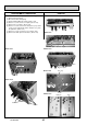
Photo 7-1
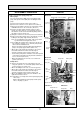
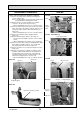
7. How to remove the booster heater
(1) Remove the front panel. (Refer to Procedure 1.)
(2) Remove the control box cover. (Refer to Procedure 3.)
(3) Disconnect the booster heater lead wires from the
CNBHT connector on the controller board and from the
BHC1 (Lead wire No.1 and No.2) and BHC2 (Lead wire
No.3 and No.4) contactors respectively. (Photo 7-1)
(4) Swing the control box to the front. (Refer to Procedure 4.)
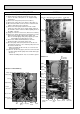
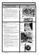
Note: Do not mix up the lead wire numbers when
re-connecting the lead wires to the contactors as
the lead wire numbers are different dependent on
the models.
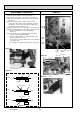
(5) Close (OFF) the pump valve (upper).
(6) Remove the two G1" nuts. (Photo 7-2)
*
When reinstalling the G1" nuts, use new G1" gaskets.
(7) Remove the flare nut (Photo 7-2).
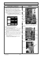
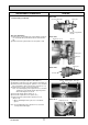
(8) Remove the two screws that hold the heater stay onto
the back panel. Lift the booster heater slightly and
remove the booster heater with the heater stay from the
back panel .
(9) Remove the 2 screws on the back of the heater stay and
remove the heater stay from the booster heater. (Photo
7-3)
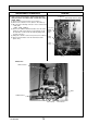
(10) Remove the drain cock (primary circuit) from the boost-
er heater. (Photo 7-2)
*
Replace the removed drain cock (primary circuit).
The drain cock can not be reused.
Model Lead wire No. Contactor
EHSC-VM6B No.1 BHC1-U
EHSC-VM6EB No.2 BHC1-V
EHPX-VM6B No.3 BHC2-U
No.4 BHC2-V
EHSC-YM9B No.1 BHC1-U
EHSC-TM9B No.2 BHC1-V
EHSC-YM9EB No.3 BHC1-W
EHPX-YM9B No.4 BHC2-U
No.5 BHC2-V
No.6 BHC2-W
EHSC-VM2B No.1 BHC1-U
EHPX-VM2B No.2 BHC1-V
ERSC-VM2B
Refer to 6. WIRING DIAGRAM
Photo 7-2
Photo 7-3
No.1
No.2 BHC1
No.3
No.4
BHC2
Flow switch
connector
(CN2F)
Cable
clamp
Cable strap
Coated clamp
Earth leakage breakers (ECB1)
Connector
(CNBHT)
Cable
clamp
Booster
heater
Drain cock
Nut (G1")
Screws
Flare nut
Pump valve
(upper)
Control box
Nut (G1")
Heater stay
Heater stay
Screw
Screw
Gasket (G1")
Gasket (G1")
* The photos shown are of the EHSC-VM6B model.
Back panel
OCH532A