
Installation manual

41
System Set Up
5
GB
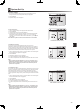
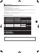
<Room Temp Control (Heating)>
This function allows operational setting of ow temperature range from the Ecodan and
also the time interval at which the FTC4 collects and processes data for the auto adap-
tation mode.
From the Operation settings menu use F1 and F2 buttons to scroll through the list
until Room temp. control (HEATING) is highlighted.
Press CONFIRM.
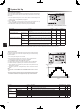
3. Use F1 and F2 keys to scroll through the menu selecting each subtitle in turn by
pressing CONFIRM. See the table below for description of each setting.
4. Enter the desired number using the function keys and press CONFIRM.
1.
2.
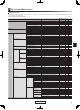
Room temp. control (HEATING) screen
Menu subtitle Function Range Unit Default
Temp. control interval Selectable according to the heat emitter type and the mate-
rials of oor (i.e. radiators, oor heating-thick, -thin concrete,
wood, etc.)
10 - 60 mins. 10
Flow temperature range Minimum temp. To minimize the loss by frequent ON and OFF in mild out-
door ambient temp. seasons.
25 - 45 ºC 30
Maximum temp. To set max. possible ow temp according to the type of heat
emitters.
35 - 60 ºC 50
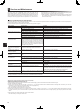
Heat pump thermo diff.adjust On/Off To minimize the loss by frequent ON and OFF in mild out-
door ambient temp. seasons.
On/Off — On
Lower limit Prohibits heat pump operation until the flow temperature
drops below the target ow temperature minus lower limit
value.
−9 - −1 ºC −5
Upper limit Allows heat pump operation until the ow temperature rises
above the target ow temperature plus upper limit value.
+3 - +5 ºC +5
*1 The minimum ow temperature that prohibits heat pump operation is 20ºC.
*2 The maximum ow temperature that allows heat pump operation equals to the maximum temperature set in the ow temp. range menu.
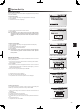
<Floor dry up function>
The Floor dry up function automatically changes the target hot water temperature
in stages to gradually dry concrete when this particular type of underoor heating
system is installed.
1. Turn off the system using the main controller.
2. From the Operation settings in the service menu, use F1 and F2 buttons to
scroll through the list until Floor dry up function is highlighted.
3. Press CONFIRM to display the FLOOR DRY UP screen.
4. To change settings, press F4. For details on settings, refer to the table below.
5. To start the Floor dry up operation, press F1 button to check a box below
*1. Upon completion of the operation the system stops all the operations except
the Freeze stat. operation.
*2. For Floor dry up function, the target ow temp. of Zone1 is the same as that of
Zone2.
Note:
This function is not available when a PUHZ-FRP outdoor unit is connect
-
ed.
Disconnect wiring to external inputs of room thermostat, demand control,
and outdoor thermostat, or the target ow temp. may not be maintained.
•
•
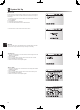
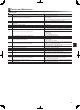
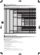
Functions Symbol Description Option/Range Unit Default
Floor dry up function a
Set the function to ON and power on the system using the main controller,
and the dry up heating operation will start.
On/Off — Off
Flow temp.
(increase)
Flow temp. increase step b Sets the increase step of the target ow temp. +1 - +10 ºC +5
Increase interval c Sets the period for which the same target ow temp is maintained. 1 - 7 day 2
Flow temp.
(decrease)
Flow temp. decrease step d Sets the decrease step of the target ow temp. −1 - −10 ºC −5
Decrease interval e Sets the period for which the same target ow temp is maintained. 1 - 7 day 2
Target temperature
Start & Finish f Sets the target ow temp. at the start and the nish of the operation. 25 - 60 ºC 30
Max. target temp. g Sets the maximum target ow temp. 25 - 60 ºC 45
Max. temp. period h Sets the period for which the maximum target ow temp. is maintained. 1 - 20 day 5
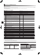
45
40
35
30
0 1 2 3 4 5 6 7 8 9 1011121314151617 18
(
°C
)
(b)
(d)
(h)
(c)
(f)
(e)
(g)
Days
Target ow temp.