
Installation manual
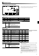

10 mm
6 mm
23
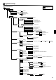
System Set Up
5
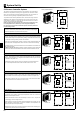
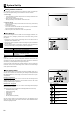
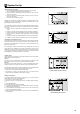
Remote Installation of Main Controller
The following instructions are related to a system controlled as in Control option D.
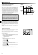
<Figure 5.3.1>
Removing main controller
Main controller
<Figure 5.3.2>
Opening the main controller
Front plate Back plate
Terminal block for controller -FTC3
connection cable
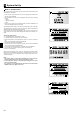
<Figure 5.3.3>
Securing the connection cable
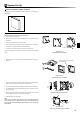
<Figure 5.3.4>
Securing the base plate to the wall
<Accessory>
Main controller cover
<Removing the main controller from the cylinder unit>
1. Open front panel of cylinder unit.
2. Remove the four screws from the metal back plate of main controller using a
screwdriver.
3. Untwist wire clip and lift off the metal back plate.
4. Gently pull apart the clips holding the main controller in place. Be careful not
to use too much force as this may break the holding clips.
5. Lift out the main controller from the front panel of the cylinder unit.
After removing the main controller, fi ll the resulting hole using the main controller
cover.
6. Separate the back and front panel using a fl at head screwdriver as shown in
Figure 5.3.
7. Fix the 2 core cable from the FTC3 into the terminal. Ensure the wires make
good contact and are securely screwed into the terminal block.
8. The inner core wires should not be visible from the outside of the back plate.
9. The sheathed cable should be pressed into the sunken channel so it is fl ush
with the base plate.
10. Once the connection cable is in place screw the back plate to the wall using
screws suitable for use on the chosen wall (local supply).
11. Finally replace the front cover plate.
Note:
Wiring for main controller cable shall be (5 cm or more) apart from power
source wiring so that it is infl uenced by electric noise form power source
wiring. (Do not insert main controller cable and power source wiring in the
same conduit.)