
Installation manual


36
The indoor cylinder unit is UNVENTED. Under UK law* the system must be
serviced once a year by a qualifi ed individual. Servicing and maintenance of the
outdoor unit should only be done by a Mitsubishi Electric trained technician with
relevant qualifi cations and experience. Any electrical work should be done by a
tradesperson with the appropriate electrical qualifi cations. Any maintenance or
‘DIY’ fi xes done by a non-accredited person could invalidate the Warranty and/or
result in damage to the cylinder unit and injury to the person.
* Building regulations – England & Wales Part G3, Scotland P3, Northern Ireland
P5. If outside of the UK please refer to local building regulations regarding un-
vented hot water storage.
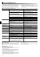
Basic Troubleshooting for Cylinder Unit
Fault symptom Possible cause Solution
Cold water at tap Direct – Booster heater cut out has triggered. Check booster heater thermostat and press reset button if safe.
Reset button is covered with white rubber cap see component
parts diagram page 7 for position.
Direct – Booster heater breaker (ECB1) has tripped. Check the cause of the trip and reset if safe.
Direct – The booster heater thermal cut-out has operated and can
not be reset using the Manual reset button.
Check the resistance of the thermal cut out, if 0 then the connec-
tion is broken and the booster heater will have to be replaced.
Please contact your Mitsubishi Electric dealer.
Direct – Immersion heater cut out has triggered. Check immersion heater thermostat and press reset button, lo-
cated on immersion heater boss, if safe. If the heater has been
operated with no water inside it may have failed, so please replace
it with a new one.
Direct – Immersion heater breaker (ECB2) has tripped. Check the cause of the trip and reset if safe.
Indirect – 3-way valve fault Check plumbing/wiring to 3-way valve.
Indirect – Heat Pump not working. Check heat pump – consult outdoor unit service manual.
All hot water used. Ensure DHW mode is operating and wait for tank to re-heat.
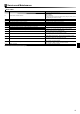
Water discharges from expan-
sion relief valve
If continual – locally supplied pressure reducing valve not working.
Check function of pressure reducing valve and replace if necessary.
If continual – expansion relief valve seat may be damaged. Remove cartridge – check seat and renew if necessary.
If intermittent – expansion vessel charge may have reduced/blad-
der perished.
Check pressure in expansion vessel. Recharge to 1 bar if neces-
sary. If bladder perished replace vessel.
Unit is being back pressurised. With cylinder cold check pressure in cylinder. If this is the same as
the incoming mains pressure then you are getting backfeed. Install
a balanced cold supply.
Water discharges from tempera-
ture and pressure relief valve
(EHPT20X-VM2HA only)
Unit has overheated – thermal controls have failed. Switch off power to the heat pump and immersion heaters. Leave
water supply on. Wait until discharge stops. Isolate water supply
and replace if faulty.
Milky/Cloudy water Oxygenated water Water from any pressurised system will release oxygen bubbles
when fl owing. The bubbles will settle out.
No hot water fl ow Cold main off. Check and open stop cock.
Strainer blocked . Isolate water supply and clean strainer.
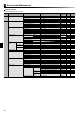
Noise during hot water draw off
typically worse in the morning
Loose airing cupboard pipework. Install extra pipe fastening clips.
Noisy pump Air in pump. Use manual and automatic air vents to remove air from system.
Top up water if necessary to achieve 1bar on primary circuit.
Pump runs for a short time for no
reason.
Pump jam prevention mechanism to inhibit the build up of scale. Normal operation no action necessary.
Hot or warm water from cold tap If tap runs cold after a minute or so the pipe is picking up heat from
heating pipe work.
Insulate/re-route pipe work.
Heating system does not get up
to set temperature.
Prohibit, schedule timer or holiday mode selected. Check settings and change as appropriate.
Incorrectly sized radiators Contact installer
The room in which the temperature sensor is located is at a differ-
ent temperature to the rest of the house.
Reposition the temperature sensor to a more suitable room.
Battery problem *wireless control only Check the battery power and replace if fl at.
Mechanical noise heard coming
from the cylinder unit.
Heaters switching on/off Normal operation no action required.
3-way valve changing position between DHW and heating (cooling)
mode.
Normal operation no action necessary.
After DHW operation room tem-
perature rises a little.
At the end of the DHW mode operation the 3-way valve diverts hot
water away from the cylinder into space heating/cooling circuit.
This is done to prevent the cylinder unit components from over-
heating. The amount of hot water directed into the space heating
circuit is dependent on the type of system and the pipe run be-
tween the plate heat exchanger and the cylinder unit.
Normal operation no action necessary.
Annual Maintenance
It is essential that the cylinder unit is serviced at least once a year by a qualifi ed
individual any spare parts required should be purchased from Mitsubishi Electric.
NEVER bypass safety devices or operate the unit without them being fully opera-
tional.
<Draining the cylinder unit>
WARNING: DRAINED WATER MAY BE VERY HOT
1. Before attempting to drain the cylinder isolate from the electrical supply to pre-
vent the immersion and booster heaters burning out.
2. Isolate cold water feed to tank.
3. Attach a hose to the tank drain cock (No. 17 on Figure 3.1). The hose should
be able to withstand heat as the emptied water could be very hot. The hose
should drain to a place lower than the tank bottom to encourage siphoning.
Open a hot water tap to start draining without a vacuum.
4. When the tank is drained close drain cock and hot tap.
5. Attach hose to booster heater drain cock and water circuit drain cock (No.13
and No. 16 on Figure 3.1). The hose should be able to withstand heat as the
emptied water could be very hot. The hose should drain to a place lower than
the booster heater drain cock to encourage siphoning.
<Annual maintenance points>
Use the Annual Maintenance Log Book as a guide to carrying out the necessary
checks on the cylinder and outdoor unit.
Service and Maintenance
7