HARDWARE MANUAL F940GOT-SWD-E/LWD-E
F940GOT-SWD-E/LWD-E Foreword • This manual contains text, diagrams and explanations which will guide the reader in the correct installation and operation of the communication facilities of FX series. • Before attempting to install or use the communication facilities of FX series this manual should be read and understood.
F940GOT-SWD-E/LWD-E F940GOT-SWD-E/LWD-E HARDWARE MANUAL Manual number : Manual revision : Date : JY992D77901 D February 2000 i
F940GOT-SWD-E/LWD-E Guidelines for the safety of the user and protection of the F940GOT-SWD-E/LWD-E This manual provides information for the installation and use of the Graphic Operation Terminal F940GOT. The manual has been written to be used by trained and competent personnel.
F940GOT-SWD-E/LWD-E Note’s on the symbology used in this manual At various times through out this manual certain symbols will be used to highlight points of information which are intended to ensure the users personal safety and protect the integrity of the equipment. Whenever any of the following symbols are encountered, its associated note must be read and understood. Each of the symbols used will now be listed with a brief description of its meaning.
F940GOT-SWD-E/LWD-E Memo iv
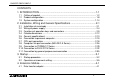
F940GOT-SWD-E/LWD-E CONTENTS 1. INTRODUCTION ...................................................................................1-1 1.1 Outline of product ................................................................................................ 1-2 1.2 Product configuration........................................................................................... 1-8 1.3 System configuration ......................................................................................... 1-14 2.
F940GOT-SWD-E/LWD-E 5. Maintenance ..........................................................................................5-1 5.1 Outline of maintenance........................................................................................ 5-1 5.2 Replacement of battery ....................................................................................... 5-3 5.3 Replacement of backlight .................................................................................... 5-5 6. Troubleshooting.......
F940GOT-SWD-E/LWD-E 1. INTRODUCTION 1. INTRODUCTION This section describes the product configuration and the system configuration of the graphic operation terminal. Confirm various functions of each unit.
F940GOT-SWD-E/LWD-E 1.1 INTRODUCTION 1. Outline of product The graphic operation terminal (which may be hereafter abbreviated as "GOT") is attached on the panel face of a control panel or an operation panel, and connected to a program connector in an FX or A Series programmable controller (which may be hereafter abbreviated as "PLC") (except the A0J2) inside the control panel.
F940GOT-SWD-E/LWD-E INTRODUCTION 1. User screens 1) Screen display function The screens created by the user can be displayed. The following functions can be assigned to each screen. And the screens to be displayed can be limited using the security function. a) Display function -Up to 500 screens created by the user can be displayed. The screens can be created using the FX-PCS-DU/WIN-E V2.00 for the DU or using the SWoD5C-GOTRE-PACK ("o" indicates a numeric not less than 1.) for the GOT.
F940GOT-SWD-E/LWD-E INTRODUCTION 1. c) Data change function -The numeric data being monitored can be changed. d) Switch function -By manipulating the operation keys in the GOT, bit devices in the PLC can be set to ON and OFF. The display panel face can be assigned as touch keys to offer the switch function. Make sure to press a touch key by fingers. If a touch key is pressed by a hard or sharp object, it may become failed.
F940GOT-SWD-E/LWD-E INTRODUCTION 1. System screens 1) Monitor function a) List program (only in the FX Series) - Programs can be read, written and monitored in the form of instruction list program. b) Buffer memory (only in the FX2N and FX2NC Series) -The contents of buffer memories (BFMs) of special blocks can be read, written and monitored.
F940GOT-SWD-E/LWD-E INTRODUCTION 1. d) Data sampling function The current value of specified data registers are acquired in a constant cycle or when the trigger condition is satisfied. -The sampling data can be displayed in the form of list or graph. -The sampling data can be output to a printer in the form of list. e) Alarm function Alarm messages can be assigned to up to 256 consecutive bit devices in the PLC.
F940GOT-SWD-E/LWD-E INTRODUCTION 1. f) Other functions Many other functions are built in. -The real-time clock is built in, and the current time can be set and displayed. -The GOT can function as an interface to enable data communication between the PLC and a personal computer in which the relay ladder creation software is started up. At this time, the GOT screen can be displayed also. -The screen contrast and the buzzer sound volume can be adjusted.
F940GOT-SWD-E/LWD-E 1.2 INTRODUCTION 1. Product configuration The GOT is equipped with accessories (1) to (3) below. Parts (4) to (8) are offered as options. 1) F940GOT (main body) F940GOT-SWD-E: 5.7" STN type LCD (with eight colors) F940GOT-LWD-E: 5.
F940GOT-SWD-E/LWD-E INTRODUCTION 1.
F940GOT-SWD-E/LWD-E INTRODUCTION 1. Optional parts 4) Software to create user screens (3.5" FD) FX-PCS-DU/WIN-E V2.10 or later (in accordance with the Windows95) SWoD5C-GOTRE-PACK ("o" indicates a numeric not less than 1.) (in accordance with the Windows95 and the WindowsNT) 5) Connection cable FX-40DU-CAB (3 m, 9.84 ft) Connection cable FX-40DU-CAB-10M (10 m, 32.81 ft) Connection cable FX-50DU-CABL (3m, 9.
F940GOT-SWD-E/LWD-E INTRODUCTION 1. 6) Connection cable FX-50DU-CAB0 (3 m, 9.84 ft) Connection cable FX-50DU-CAB0-1M (1 m, 3.28 ft) Connection cable FX-50DU-CAB0-10M (10 m, 32.81 ft) Connection cable FX-50DU-CAB0-20M (20 m, 65.62 ft) Connection cable FX-50DU-CAB0-30M (30 m, 98.43 ft) Connection cable FX-50DU-CAB0L (3 m, 9.84 ft, with L-shape connector on the GOT side) Each of them is an optional cable to connect the GOT and the FX0/FX0S/FX0N/FX2N/FX2NC Series PLC.
F940GOT-SWD-E/LWD-E INTRODUCTION 1. 8) Battery PM-20BL (spare part) This is used to back up the alarm history data, the real-time clock, etc. This is attached when the GOT is delivered. 9) EPROM memory to store the user screen data FX-EPROM4M This is an optional EPROM memory (M27C4002-**F (4 MB) manufactured by SGS-THOMSON) to save the user screen data. The user screen data can be written using a general-purpose ROM writer connected to the screen creation software.
F940GOT-SWD-E/LWD-E INTRODUCTION 1. 10) Data transfer adaptor F9GT-40UMB This is an optional adaptor to connect the FX-EPROM-4M 9) and transfer the user screen data to the flush memory inside the GOT. When a same screen is to be transferred to two or more GOT units, transfer can be performed quickly and easily using this adaptor compared with the screen creation software. 11) Protection sheet F9GT-40PSC (5 sheets) This optional sheet protects the display screen against dirt. Adhere it on the screen.
F940GOT-SWD-E/LWD-E 1.3 INTRODUCTION 1. System configuration The system configuration to use the GOT is described below. When the GOT is directly connected to the PLC F940GOT-SWD-E/LWD-E :When the GOT is connected via a computer link unit, refer to Section 2.
F940GOT-SWD-E/LWD-E INTRODUCTION 1. Peripheral units for GOT General-purpose personal computer (screen creation software) 1 Data transfer cable F2-232CAB-1 (when the RS-232C connector in the personal computer is 25-pin type) Connected to RS-232C connector in GOT Screen creation software for DU FXPCS-DU/WIN-E (V2.10 or later) Screen creation software for A900GOT SW D5C-GOTRE-PACK (" " is a numeric not less than 1.
F940GOT-SWD-E/LWD-E INTRODUCTION 1. The figure below shows connection to peripheral units used to create sequence programs. When built-in two-port interface function is used F940GOT-SWD-E/LWD-E When the two-port interface function is used, the operation environment should be set. (Refer to the description on "SERIAL PORT" on the SET-UP MODE screen.
F940GOT-SWD-E/LWD-E INTRODUCTION 1. Peripheral unit to create sequence programs General-purpose personal computer 1 * A general-purpose computer can be directly connected, and both the GOT and the personal computer can be used at the same time (without using the FX-2PIF). When the two-port interface function is used using the software package SW D5C(F)-GPPW-E, make sure to use the connection cable having the model name shown on the left to connect a personal computer.
F940GOT-SWD-E/LWD-E INTRODUCTION 1.
F940GOT-SWD-E/LWD-E INTRODUCTION 1. Peripheral unit to create sequence programs Handy programming panel FX-10P-E/20P-E 1 (A Series cannot be used.) A7PHP/A7HGP A6GPP/A6PHP The FX2N/FX2NC Series can be used in the instruction/device range of the FX Series. 2 Note: The two-port interface FX-2PIF is available in CPU port connection (via the RS-422). This interface is not available in computer link connection (via the RS-422 or the RS-232C) and CPU port connection (via the RS-232C).
F940GOT-SWD-E/LWD-E INTRODUCTION 1.
F940GOT-SWD-E/LWD-E 2. Installation, Wiring and General Specifications 2. Installation, Wiring and General Specifications This section describes installation of the GOT and wiring of the power supply. 2.1 Installation of main body Caution on installation • Use the unit in the environment for the general specifications described in the manual.
F940GOT-SWD-E/LWD-E Installation, Wiring and General Specifications 2. The GOT is to be embedded in a panel. Perform the installation procedure described below. On the panel face, drill a mounting hole of the dimensions shown on the right. +0.04 121 +1 -0 (4.76 - 0.00 ) 1) Machining the mounting panel face mm (inches) * Make sure that the plate thickness of the mounting panel is 5 mm (0.2 inches) or less. 153 -+10 (6.02 -+0.04 0.
F940GOT-SWD-E/LWD-E Installation, Wiring and General Specifications 2. 3) Fixing the GOT Hang the hook of each metal fixture (offered as accessory) to a mounting hook hole in the GOT. Tighten a mounting bolt (offered as accessory) securely in each position. Enlarged view The GOT can be fixed in four positions at corners. However, to prevent dusts and water, fix the GOT in six positions. b) a) Metal fixture a) b) Tightening bolt * Make sure that the tightening torque for each tightening bolt is 0.
F940GOT-SWD-E/LWD-E 2.2 Installation, Wiring and General Specifications 2. Wiring of power supply Cautions on Wiring • Make sure to shut down the power supply outside the unit before starting installation or wiring.If the power supply is not shut down outside, electrical shock or damages of the unit may be caused. CAUTION • Connect the DC power cable to a dedicated terminal as described in this manual.
F940GOT-SWD-E/LWD-E Installation, Wiring and General Specifications 2. The power is supplied to the GOT from a PLC or an external power supply unit. • Connection examples 1) When the power is supplied from an FX Series PLC (Refer to "Cautions on connection" in the next page.) Connect the power terminal in the GOT to the 24V DC service power supply in the PLC basic unit or PLC extension unit.
F940GOT-SWD-E/LWD-E Installation, Wiring and General Specifications 2. 2) When the power is supplied from an external power supply unit Connect the power terminal provided on the rear face of the GOT to the 24V DC terminal in the external power supply unit.
F940GOT-SWD-E/LWD-E Installation, Wiring and General Specifications 2. • Specifications of power supply unit Item Supply voltage Power ripple Current consumption Specifications F940GOT-LWD 24V DC F940GOT-SWD +10% -15% 200mV or less 390mA / 24V DC 410mA / 24V DC Allowable instantaneous Operation shall be continued against instantaneous power interruption duration power interruption for less than 5 ms.
F940GOT-SWD-E/LWD-E Installation, Wiring and General Specifications 2. Cautions on connection • The current consumption of the GOT is as shown in the table above. When supplying the power to the GOT from the 24V DC service power in the FX Series PLC basic unit or extension unit, take into account the total current supplied to proximity switches and extension blocks. If the total current exceeds the capacity of the service power, the GOT should obtain the power from an external power supply unit.
F940GOT-SWD-E/LWD-E Functions of operation keys and connectors 1) Front panel a) a) Display unit Allows graphic display of 320 × 240 dots. Character string: 20 full-width characters × 15 lines 40 half-width characters × 15 lines Alphabets, numerics, Katakana characters and Kanji characters (JIS Level 1) can be displayed in the size of ×1 to ×4 in each of the vertical and horizontal directions. POWER 162 (6.
F940GOT-SWD-E/LWD-E Installation, Wiring and General Specifications 2. 2) Rear panel a) Power terminal Supplies the power to the GOT, and allows grounding. c) b) b) Battery PM-20BL Backs up the sampling data, the alarm history and the current time. The screen data is stored in the built-in flush memory, and does not require the battery. a) 24VDC c) Extension interface Connects an optional extension equipment.
F940GOT-SWD-E/LWD-E Installation, Wiring and General Specifications 2. 3) Connectors provided on the side Used when a printer is connected or when a PLC is connected via a computer link unit. b) RS422 b) Connects a personal computer to transfer to the PLC the screen data created by the screen creation software and sequence programs using the two-port interface function.
F940GOT-SWD-E/LWD-E Outside dimensions 57 (2.24) RS232C 120 (4.72) 5 (0.20) 130 (5.12) 2.4 Installation, Wiring and General Specifications 2. RS422 POWER 152 (5.98) 162 (6.38) Outside painting color: Munsell 0.08GY 7.64/0.81 Mass: Approximately 1.0 kg including metal fixtures (0.1 kg) +1 +1 Panel cut dimensions: 153 -0 × 121 -0 Unit: mm (inches) +0.04 +0.04 (6.02 -0.00 × 4.76 -0.
F940GOT-SWD-E/LWD-E 2.5 Installation, Wiring and General Specifications 2. General specificationsl During operation: 0 to +50°C (0 to +40°C when extension interface is used) Ambient temperature During storage: -20 to +60°C Ambient humidity During operation: 35 to 85%RH (Condensation shall not be allowed.) Frequency Acceleration Amplitude Vibration resistance In accordance with JIS B3501 and IEC 1131-2 When intermittent 10-57Hz - 0.075mm vibrations are applied 57-150Hz 9.
F940GOT-SWD-E/LWD-E Installation, Wiring and General Specifications 2. Supply voltage 24V DC +10%, -15% Current consumption: 390 mA/24V DC (F940GOT-LWD-E) 410 mA/24V DC (F940GOT-SWD-E) Display element STN type full-dot matrix LCD, monochrome (F940GOT-LWD-E) or color (F940GOT-SWD-E) Screen Service life Backlight Key LCD of 320 x 240 dots, 20 full-width characters × 15 lines, Effective display size: 115 × 86 mm (5.
F940GOT-SWD-E/LWD-E 2.6 Installation, Wiring and General Specifications 2. Connection to personal computer Use the following cable to connect a personal computer.
F940GOT-SWD-E/LWD-E Installation, Wiring and General Specifications 2.
F940GOT-SWD-E/LWD-E Installation, Wiring and General Specifications 2.
F940GOT-SWD-E/LWD-E 2.7 Installation, Wiring and General Specifications 2. CPU port connection Use either of the following cables to connect the PLC directly.
F940GOT-SWD-E/LWD-E Installation, Wiring and General Specifications 2.
F940GOT-SWD-E/LWD-E Installation, Wiring and General Specifications 2. Pin assignment and connection diagram of connection cables (The connection cables are offered as options.
F940GOT-SWD-E/LWD-E Installation, Wiring and General Specifications 2. • When the CPU in the FX/A Series PLC is directly connected, up to four GOT units can be connected to one PLC (1-to-N connection). As the connection type, select "CPU PORT (RS232C)" or "CPU PORT (RS422)" in "CONNECTION" on the PLC TYPE screen. System configuration FX/A Series Side of GOT 1st unit RS-422 communication Maximum extension distance: 30 m (98.
F940GOT-SWD-E/LWD-E Installation, Wiring and General Specifications 2. Connection cable examples: 1st GOT: FX-50DU-CAB0 (equivalent to connection cable for PLC) 2nd GOT: FX-232CAB-1 3rd GOT: Cable created by user (Refer to the connection diagram.) 4th GOT: FX-232CAB-1 Connection diagram 1 2 3 4 5 6 7 8 9 1 2 3 4 5 6 7 8 9 Communication speed: The communication speed with the PLC becomes slower as the number of connected GOT units becomes larger.
F940GOT-SWD-E/LWD-E Installation, Wiring and General Specifications 2. • In the case of the FX2N Series, communication can be performed by CPU port connection (RS-232C communication) using the FX2N-232-BD. In this case also, In the case of the FX2N Series, communication can be performed by CPU port connection (RS-232C communication) using the FX2N-232-BD. In this case also, up to four GOT units can be connected to one PLC (1-to-N connection).
F940GOT-SWD-E/LWD-E Installation, Wiring and General Specifications 2. Connection cable examples: 1st GOT: FX-232CAB-1 2nd GOT: Cable created by user (Refer to the connection diagram.) 3rd GOT: FX-232CAB-1 4th GOT: Cable created by user (Refer to the connection diagram.) Connection diagram 1 2 3 4 5 6 7 8 9 1 2 3 4 5 6 7 8 9 Communication speed: The communication speed with the PLC becomes slower as the number of connected GOT units becomes larger.
F940GOT-SWD-E/LWD-E Installation, Wiring and General Specifications 2. When two or more GOT units are connected to the FX/A/QnA Series PLC, communication is performed in the location sequence from the GOT unit nearest to the CPU (that is, in the sequence of the 1st, 2nd, 3rd and 4th GOT units). Accordingly, when turning on the power of the GOT units for the first time, turn on the power from the one nearest to the CPU.
F940GOT-SWD-E/LWD-E 2.8 Installation, Wiring and General Specifications 2. Computer link port connection (MELSEC A Series) The GOT can be connected to the MELSEC A Series via a computer link unit as shown below. • Applicable PLC units and computer link units < A Series > AJ71UC24 A1SCPU24-R2 A1SJ71UC24-R2/R4/PRF A1SJ71C24-R2/R4/PRF A2CCPUC24 (PRF) For the communication setting for the computer link unit, refer to the F940GOT Operation Manual offered separately.
F940GOT-SWD-E/LWD-E Installation, Wiring and General Specifications 2. • Connect the GOT to the computer link unit (PLC) as shown below. < For RS-422 communication > Computer link unit side (PLC side) Terminal block 1 6 2 7 5 RDA RDB SDA SDB SG GOT side 5 4 3 2 1 9 8 7 6 D-sub (male) 9-pin < For RS-232C communication > The connection cable F2-232CAB is also available.
F940GOT-SWD-E/LWD-E Installation, Wiring and General Specifications 2.
F940GOT-SWD-E/LWD-E 2.9 Installation, Wiring and General Specifications 2. Connection to SYSMAC C Series The GOT can be connected to the SYSMAC C Series manufactured by OMRON via a host link unit as shown below. • Applicable PLC units and host link units < SYSMAC C Series > A host link unit or a CPU equipped with an interface for host link is required. For the setting of the host link unit, refer to the F940GOT Operation Manual offered separately.
F940GOT-SWD-E/LWD-E Installation, Wiring and General Specifications 2. • Connect the GOT to the host link unit (SYSMAC C Series) as shown below. For connection of a model not shown in the examples below, refer to the manual of the C Series link unit.
F940GOT-SWD-E/LWD-E Installation, Wiring and General Specifications 2.
F940GOT-SWD-E/LWD-E 2.10 Installation, Wiring and General Specifications 2. Connection to FLEX-PC N Series The GOT can be connected to the FLEX-PC N Series manufactured by FUJI Electric via a link unit shown below. • Connection type Link port connection (RS-422) Link port connection (RS-232C) CPU port connection (RS-232C) Select the connection type using the operation environment setting described in the next section or the screen creation software.
F940GOT-SWD-E/LWD-E Installation, Wiring and General Specifications 2. • Link unit - NB Series NB-RS1-AC, NB-RS1-DC - NJ Series NJ-RS2, NJ-RS4 - NS Series NS-RS1 - CPU in which RS-232C interface is built in NJ-CPU-B16 • Connection diagram Connect the GOT and the link unit (PLC) as shown below.
F940GOT-SWD-E/LWD-E Installation, Wiring and General Specifications 2.
F940GOT-SWD-E/LWD-E 2.11 Installation, Wiring and General Specifications 2. Connection by general-purpose communication The GOT can be connected to a general controller such as micro computer board. (The connected controller is hereafter referred to as "host (unit)".) • Outline In genera-purpose communication, the host unit is connected to the GOT via the RS-232C and functions as the parent station in communication. Inside the GOT, there is a data area to hold word data and bit data.
F940GOT-SWD-E/LWD-E Installation, Wiring and General Specifications 2. Accordingly, to display the data stored in the host unit on the screen, the host unit should transfer the data to the data area inside the GOT using write commands. The transfer destination is a location specified by the screen data. The data change result by manipulation of keys can be transferred from the data area inside the GOT to the host unit if the host unit gives read commands.
F940GOT-SWD-E/LWD-E Installation, Wiring and General Specifications 2. • Connection diagram Connect the GOT and the host unit as shown below. FG SD RD Host side SG 1 2 3 7 8 6 4 5 GOT side 5 4 3 2 1 9 8 7 6 D-sub (male) 9-pin * The control lines RTS, CTS, DTR and DSR are not used.
F940GOT-SWD-E/LWD-E Installation, Wiring and General Specifications 2. • Communication setting The setting related to communication can be performed using the screen creation software or the GOT main body. To use general-purpose communication, - Screen creation software: Set the connected personal computer to "General-Purpose Communication". - GOT main body: Select "SET-UP MODE", "PLC SYSTEM" and "GENERAL-PURPOSE COMMUNICATION" in this order.
F940GOT-SWD-E/LWD-E 3. Startup 3. Startup This section describes the startup procedure from turning on of the power of the GOT to selection of the mode. This section describes also the environment setting important to use of the GOT. Make sure to read this section carefully.
F940GOT-SWD-E/LWD-E 3.1 Startup 3. Startup procedure This paragraph describes the startup procedure from turning on of the power of the GOT to selection of the mode. Perform wiring of the power supply unit of the GOT. Connect the PLC. Turn on the power without pressing the touch key. Turn on the power while pressing the touch key. The OPENING SCREEN is displayed. The SET-UP MODE screen is displayed. 1 •Perform wiring of the power supply unit of the GOT. (Refer to Section 2.
F940GOT-SWD-E/LWD-E Startup 3. 1 A user screen is displayed. •A user screen is displayed. If any user screen has not been created, the SELECT MODE screen is displayed as follows. When there is no screen data The SELECT MODE screen is displayed. 2 •The SELECT MODE screen is displayed. Each menu item on the screen functions as a touch key. When a desired one is pressed, the corresponding mode is selected.
F940GOT-SWD-E/LWD-E Startup 3.
F940GOT-SWD-E/LWD-E 3.2 Startup 3. Operation environment setting The operation environment setting function performs initial setting important to operation of the GOT. The SET-UP MODE screen can be displayed by turning on the power while pressing and holding the upper left corner of the screen in accordance with "3.1 Startup procedure" or by selecting "SET-UP MODE" on the OTHER MODE screen.
F940GOT-SWD-E/LWD-E Startup 3. The areas enclosed with broken lines function as touch keys. (Broken lines are not actually displayed on the screen.) a) LANGUAGE Allows to set the language displayed on the system screens such as Japanese and English. b) PLC TYPE Allows to set the connected PLC type. c) SERIAL PORT To be selected when a printer is connected to the GOT or when communication is performed between the GOT and a micro computer board.
F940GOT-SWD-E/LWD-E Startup 3. h) BUZZER Allows to set the buzzer sound issued when a key is pressed. i) LCD CONTRAST Allows to set the LCD brightness. j) CLEAR USER DATA Deletes the user screen data. k) END Exits the SET-UP MODE screen. l) Cursors Change over the menu item on the SET-UP MODE screen.
F940GOT-SWD-E/LWD-E Startup 3. Each setting screen is displayed as shown below. On each screen, when the END key at the upper right corner is pressed after setting is completed, the SET-UP MODE screen is displayed. • Set the language used on the system screens and the user screens. [ PLC TYPE screen ] [ PLC TYPE ] END SYSTEM LANGUAGE: ENGLISH a) CHARACTER SET: ENGLISH b) a) SYSTEM LANGUAGE Allows to set the language displayed on the system screens and in error messages.
F940GOT-SWD-E/LWD-E Startup 3. [ PLC TYPE screen ] a) PLC TYPE Allows to select either one among FX SERIES, A SERIES, C SERIES (manufactured by OMRON), N SERIES (manufactured by FUJI Electric) and UNIVERSAL (general-purpose communication). END [ PLC TYPE ] PLC TYPE: FX SERIES a) CONNECTION: CPU PORT b) STATION #: * * c) b) CONNECTION Allows to set the connection method of the PLC selected in 1] above. • Select the connected PLC type.
F940GOT-SWD-E/LWD-E Startup 3. c) STATION # Allows to set the station No. of the link unit connected to the GOT when "LINK PORT" is selected in 2] above.
F940GOT-SWD-E/LWD-E Startup 3. [ SERIAL PORT] •Set the serial communication parameters for the printer used to print out alarm messages and sampling data. END [ SERIAL PORT] SPEED : 9600 bps DATA BIT : 7 bit STOP BIT : 1 bit PARITY : Even •Make sure to set "PRINTER" to "USE" when a printer is connected. When it is set to "USE", the two-port interface function is not available. HANDSHAKING : XON/XOFF PRINTAER : NOT USED •The areas enclosed with broken lines function as touch keys.
F940GOT-SWD-E/LWD-E Startup 3. [ OPENNING SCREEN ] END [ OPENNING SCREEN ] DISPRAY TIME 20 SEC. •Set the duration in the unit of second in which the OPENING SCREEN screen indicating the model name, the version, etc. is displayed when the power is turned on. •When the touch key "DISPLAY TIME" is pressed, the time can be set using the ten-key pad displayed at the bottom of the screen.
F940GOT-SWD-E/LWD-E Startup 3. [ MENU CALL ] [ MENU CALL KEY screen ] SELECT CALL KEY LOCATION END •Set the menu call key which changes over the screen mode (in which a user screen is displayed) to the SELECT MODE screen. The menu call key is mesh type, and 2 x 2 in size. • One or two corners can be selected among the four corners of the screen. • When the menu call key is not set, only the screen mode is available. Any other mode is not available.
F940GOT-SWD-E/LWD-E Startup 3. [ SET CLOCK ] END [ SET CLOCK ] DATE 1 / 3 / 1999 TIME 10: 10: 10 • Set the time used in the time switch, the sampling mode and the alarm mode. •When "DATE" or "TIME" is selected, date or time can be entered using the ten-key pad displayed at the bottom of the screen. Enter the desired date or time, and press the ENT key to register it.
F940GOT-SWD-E/LWD-E Startup 3. [ SET BACKLIGHT ] END [ SET BACKLIGHT ] OFF TIME 10 MIN. 5 6 7 8 9 CLR 0 1 2 3 4 ENT •Set the time at which the backlight of the display screen becomes extinguished. When a touch key is not pressed or the user screen is not changed over within the specified OFF time, the backlight becomes extinguished. •When "OFF TIME" is pressed, the OFF time can be set within the range of 0 to 99 minutes using the ten-key pad displayed at the bottom of the screen.
F940GOT-SWD-E/LWD-E Startup 3. [ BUZZER ] END [ BUZZER ] •Set whether or not the buzzer sound is to be issued when a key is pressed or an error occurs. •Select "BUZZER ON" or "BUZZER OFF". BUZZER ON BUZZER OFF [ LCD CONTRAST ] [ LCD CONTRAST ] END •The LCD brightness can be set in 15 steps. When the key is pressed, the LCD becomes darker. When the key is pressed, the LCD becomes brighter.
F940GOT-SWD-E/LWD-E Startup 3. [ CLEAR USER DATA] [ CLEAR USER DATA] OK TO CLEAR USER DATA? YES •The screen data stored in the GOT can be cleared. END •When "YES" is selected, the message "NOW CLEARING USER DATA" is displayed and no key is accepted. When the message "COMPLETED!" is displayed, the data is cleared completely.
F940GOT-SWD-E/LWD-E Startup 3.
F940GOT-SWD-E/LWD-E 4. Extension Module 4. Extension Module This section describes handling of the extension module interface provided on the rear face of the GOT. 4.1 Data transfer adaptor The data transfer adaptor F9GT-40UMB is used to store the user screen data stored in the EPROM for user screen data FX-EPROM-4M to the flush memory in the GOT. (The user screen data can be written to the EPROM using the screen creation software.
F940GOT-SWD-E/LWD-E Extension Module 4. Operating procedure a) a)FX-EPROM-4M c) b) b)F9GT-40UMB c)User screen/system screen selector switch d)Extension module interface d) 1)Attach the FX-EPROM-4M a) in which user screens are saved to the F9GT-40UMB b). Pay rigid attention not to bend leads of the FX-EPROM-4M a) nor touch them with bare fingers. 2)Put upward the user screen/system screen selector switch c).
F940GOT-SWD-E/LWD-E Extension Module 4. 5)When transfer is finished, make sure to turn off the power of the GOT and remove the adaptor b).
F940GOT-SWD-E/LWD-E Extension Module 4.
F940GOT-SWD-E/LWD-E 5. Maintenance 5. Maintenance This section describes maintenance such as replacement of the battery and the backlight. 5.1 Outline of maintenance Cautions on startup and maintenance • Connect correctly the battery for memory backup. Never charge, disassemble, heat, put into fire nor short-circuit the battery for memory backup. If the battery for memory backup is handled in such a way, it may be burst or take fire.
F940GOT-SWD-E/LWD-E Maintenance 5. CAUTION • Make sure to turn off the power before attaching or removing an extension module. If an extension module is attached/removed while the power is supplied, the contents stored in the memory or the EPROM memory itself may be damaged. • Never disassemble nor modify the unit. If the unit is disassembled or modified, failure, malfunction or fire may be caused. * For repair, contact MITSUBISHI ELECTRIC SYSTEM SERVICE.
F940GOT-SWD-E/LWD-E 5.2 Maintenance 5. Replacement of battery When the battery voltage drops, the control devices for system information set by the screen creation software becomes ON. The control devices are interlocking with auxiliary relays in the PLC. It is recommended to attach a lamp using the output of the PLC so that the ON/OFF status of the 7th bit can be monitored from the outside. For the details of control devices, refer to the Operation Manual. Example :When the FX-PCS-DU/WIN are used.
F940GOT-SWD-E/LWD-E Maintenance 5. The alarm history and the sampling data are held for approximately 1 month after the control device for battery voltage drop becomes ON. After 1 month, these data cannot be held. It is recommended to replace the battery soon. a) a) Battery PM-20BL 1) Turn off the power of the GOT. 2) Open the small window provided on the rear panel. 3) Remove the current battery from the holder. Disconnect the connector. 4) Within 30 seconds, connect the connector of a new battery.
F940GOT-SWD-E/LWD-E 5.3 Maintenance 5. Replacement of backlight Replace the backlight F9GT-40LTS using the following procedure. Replacement procedure a) a)Mounting screw b)Backlight connector c)Backlight F9GT-40LTS d)Backlight fixing holder 1) Make sure that the power of the GOT is turned off. Remove the mounting screws a) located at four corners, and slowly remove the rear panel.
F940GOT-SWD-E/LWD-E Maintenance 5.
F940GOT-SWD-E/LWD-E 6. Troubleshooting 6. Troubleshooting This section describes troubleshooting during operation. 6.1 Power indication When an abnormality has occurred, check the following points. The POWER LED in the GOT is lit by the 5 V power supply inside the GOT. When the POWER LED is extinguished, nothing is displayed on the screen or no key is accepted, the power supply may be insufficient. Especially when the power is supplied from the FX Series PLC, the following points are suspected.
F940GOT-SWD-E/LWD-E Troubleshooting 6. The table below shows the list of error messages displayed during manipulation and operation of the GOT. Confirm the contents of an error, and take appropriate actions. Error message Contents Actions CAN NOT The PLC is running in the EPROM mode. Set the PLC to the RAM mode. WRITE TO PLC Or the protect switch of the EEPROM is Or set to OFF the protect switch of the set to ON. EEPROM. MEMORY. PLC IS RUNNING. DATA IS NOT FOUND.
F940GOT-SWD-E/LWD-E Error message Troubleshooting 6. Contents Actions The power supply of the PLC is set to OFF. Set to ON the power of the PLC. COMMUNICATION ERROR OCCURS.*1 The cable is imperfectly connected or Connect the cable correctly. defective. Or replace the cable with a new one. Manipulate the personal computer again. The power of the PLC was set to OFF Remove the cause of flashing of the LED, while communication was performed.
F940GOT-SWD-E/LWD-E Error message Troubleshooting 6. Contents Actions CAN NOT USE An entry code has been registered in the Unlock or delete the entry code in "ENTRY CODE" on the OTHER MODE THE FUNCTION. PLC. screen. The created screen data is destroyed. Clear all data by pressing the ACK key. * When it is difficult to search the changed data, it is recommended to write the data again to the GOT from the screen data backup file created using the screen creation software.
F940GOT-SWD-E/LWD-E Additional Functions (in Ver3.00 or later) 7. 7. Additional Functions (in Ver3.00 or later) 7.1 Applicable Versions and Models Table 7.1 : Model name F940GOT-SWD-E, F940GOT-LWD-E Version Unit manufactured in July, 1999 or later (whose manufacturer’s serial No. is "97***" or later) Ver. 3.00 or later Contents of Additional Functions 1) MELSEC QnA Series PC can be connected. CPU direct connection (RS-422) and computer link connection (RS-422, RS-232C) are available.
F940GOT-SWD-E/LWD-E 7.2 Additional Functions (in Ver3.00 or later) 7. Connection to MELSEC QnA Series PC • Applicable PCs QnA, Q2AS CPU direct connection (RS-422) Computer link correction (RS-422, RS-232C) AJ71QC24, AJ71QC24-R2, AJ71QC24-R4 A1SJ71QC24, A1SJ71QC24-R2 * Connection is same as that of the A Series except computer link connection via the RS422 interface whose connector is D-sub, 25-pin type. Refer to connection diagrams of the A Series.
F940GOT-SWD-E/LWD-E 7.3 Additional Functions (in Ver3.00 or later) 7. Connection to SLC 500 Series The SLC 500 Series PC manufactured by Allen-Bradley can be connected using a programming connector in the PC. • Applicable PCs SLC5/03, SLC5/04 CPU direct connection (RS-232C) For the communication setting, refer to the F940GOT Operation Manual.
F940GOT-SWD-E/LWD-E Additional Functions (in Ver3.00 or later) 7. • Connect the GOT and the SLC Series PC as shown below. For the cable length and the detailed specifications of the SLC Series, refer to the manual of the SLC Series.
F940GOT-SWD-E/LWD-E 7.4 Additional Functions (in Ver3.00 or later) 7. Connection to Bar Code Reader The F940-GOT can be connected to a bar code reader. • Applicable bar code readers The F940-GOT can be connected to any bar code reader whose communication specifications and data format are as shown below. Table 7.2 :Communication specifications Communication port RS232C Communication baud rate 9600bps Data length 8 bit Stop bit length 1 bit Parity Even Table 7.
F940GOT-SWD-E/LWD-E Additional Functions (in Ver3.00 or later) 7. • System configuration • Connection 5 4 3 2 1 9 8 7 6 1:None 2:RD(RXD) 3:SD(TXD) 4:DTR 5:SG 6:DSR 7:RTS 8:CTS 9: --- * Because the RS-232C connector is used to connect a bar code reader, the printout function and the two-port interface function are not available while a bar code reader is connected. When the F940GOT is connected to a PC unit via RS-232C, any bar code reader cannot be connected.
F940GOT-SWD-E/LWD-E 7.5 Additional Functions (in Ver3.00 or later) 7. Screen Hard Copy Function The screen being displayed can be output to a printer. • Applicable printers Printer with ESC/P J84, RS-232C interface * Verified printer model name LBP450 (A4 laser printer) manufactured by CANON • Printable screens User screens (in the screen mode) System screens cannot be printed out.
F940GOT-SWD-E/LWD-E 7.6 Additional Functions (in Ver3.00 or later) 7. Additional Function in Alarm History Display • The following touch keys (key codes) are added in the alarm history display function. Table 7.4: Key code FFB6 (H) FFB7 (H) Description of function Deletes displayed alarms selected on the While alarm devices are set to ON, screen. selected alarms or the entire alarm history is not deleted. Deletes the entire alarm history.
F940GOT-SWD-E/LWD-E 8. Additional Functions (in V3.10 or later) 8.1 Applicable Versions and Models Additional Functions (in V3.10 or later) 8. • Versions F940GOT-SWD-E: Unit manufactured in October, 1999 or later F940GOT-LWD-E (Whose manufacturer’s SERIAL No.9X**** or later) • Software SW3D5C-GOTRE-PACK Version.
F940GOT-SWD-E/LWD-E Additional Functions (in V3.10 or later) 8.
F940GOT-SWD-E/LWD-E 9. Additional Functions (in V4.00 or later) 9.1 Applicable Versions and Models Additional Functions (in V4.00 or later) 9. • Versions F940GOT-SWD-E: Unit manufactured in January, 2000 or later F940GOT-LWD-E (Whose manufacturer’s SERIAL No.01**** or later) • Software SW4D5C-GOTRE-PACK Version.
F940GOT-SWD-E/LWD-E Additional Functions (in V4.00 or later) 9.
Under no circumstances will MITSUBISHI ELECTRIC be liable responsible for any consequential damage that may arise as a result of the installation or use of this equipment. All examples and diagrams shown in this manual are intended only as an aid to understanding the text, not to guarantee operation. MITSUBISHI ELECTRIC will accept no responsibility for actual use of the product based on these illustrative examples.
HARDWARE MANUAL F940GOT-SWD-E/LWD-E HEAD OFFICE: MITSUBISHI DENKI BLDG MARUNOUCHI TOKYO 100-8310 TELEX: J24532 CABLE MELCO TOKYO HIMEJI WORKS: 840, CHIYODA CHO, HIMEJI, JAPAN JY992D77901D (MEE0002) Effective FEB. 2000 Specification are subject to change without notice.