
Instruction manual

PROTECTIVE FUNCTIONS
151
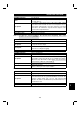
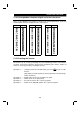
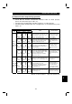
5.1.6 How to Check for Error using the LEDs
(1) When one inverter is connected
The following example indicates the causes of faults which may be judged from the
operating status indicator LED states of the inverter under the condition that the
SW, M/S and PRM LEDs of the master unit are off (the master unit setting is
correct) in the system configuration where one inverter is connected.
CPUPower
supply
Master
unit
Station 1
Inverter
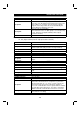
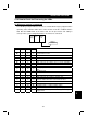
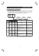
LED States
L. RUN SD RD L. ERR
Cause
!
"""
Normal communication is made but CRC error has
occurred due to noise.
!
""#
Normal communication
!
"#"
Hardware fault
!
"##
Hardware fault
!
#""
Cannot answer due to CRC error of receive data.
!
#"#
Data sent to the host station does not reach destination.
!
##"
Hardware fault
!
###
Hardware fault
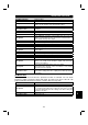
#"""
Polling response is made but refresh receive is in CRC
error.
#""#
Hardware fault
#"#"
Hardware fault
#"##
Hardware fault
##""
Data sent to the host station is in CRC error.
##"#
There is no data sent to the host station, or data sent to
the host station cannot be received due to noise.
####
Hardware fault
####
Cannot receive data due to open cable, etc.
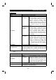
##"#
!
Invalid baud rate or station number setting
!
"""
Baud rate or station number changed during operation.
###
!
WDT error occurrence (hardware fault), power off, power
supply failure
!
: On,
#
: Off,
"
: Flicker
5