
Instruction manual


INSTALLATION AND WIRING
21
(
3
)
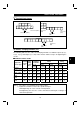
Wiring method
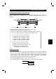
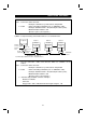
1) For wiring the control circuit, use cables after stripping their sheaths.
Refer to the gauge printed on the inverter and strip the sheaths to the following
dimensions. If the sheath is stripped too much, its cable may be shorted with the
adjoining cable. If the sheath is stripped too little, the cable may come off.
7mm
±
1mm
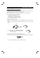
2) When using bar terminals and solid wires for wiring, their diameters should be
0.9mm maximum. If they are larger, the threads may be damaged during tightening.
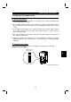
3) Loosen the terminal screw and insert the cable into the terminal.
4) Tighten the screw to the specified torque.
Undertightening can cause cable disconnection or misoperation. Overtightening can
cause damage to the screw or unit, leading to short circuit or misoperation.
Tightening torque: 0.25 N
⋅
m to 0.49 N
⋅
m
* Use a size 0 screwdriver.
Note : When routing the stripped cables, twist them so that they do not become loose.
In addition, do not solder it.
(
4
)
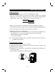
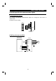
Control logic changing
The input signal logic is factory-set to the sink mode.
To change the control logic, the position of the connector beside the control circuit
terminal block must be changed.
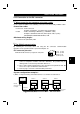
1) Using tweezers etc. to remove the connector in the sink logic position and fit it in the
source logic position.
Do this position changing before switching power on.