
Instruction manual


INSTALLATION AND WIRING
24
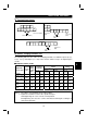
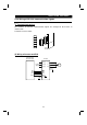
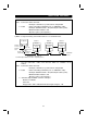
(3) Connection of two or more inverters
Factory Automation can be applied to several inverters which share a link system as
CC-Link remote device stations and are controlled and monitored by PLC user
programs.
DA
DB
DG
SLD
FG
Inverter
DA
DB
DG
SLD
FG
DA
DB
DG
SLD
FG
InverterMaster module
Terminal
resistor*
Terminal
resistor*
Shielded twisted
cable
Shielded twisted
cable
*Use the terminal resistors supplied with the PLC.
1) Maximum number of units connected to one master station
42 units (when only inverters are connected)
If there are other units, the following conditions must be satisfied
since the number of stations occupied changes with the unit:
{(1
×
a) + (2
×
b) + (3
×
c) + (4
×
d)}
≤
64
a: Number of units occupying 1 station
b: Number of units occupying 2 stations
c: Number of units occupying 3 stations
d: Number of units occupying 4 stations
{(16
×
A) + (54
×
B) + (88
×
C)}
≤
2304
A: Number of remote I/O station
≤
64
B: Number of remote device stations
≤
42
C: Number of local, standby master
and intelligent device stations
≤
26
(
4
)
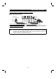
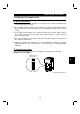
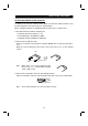
Wiring method
1) 1) Use twisted cables (three wire type) after stripping the cable sheaths and twisting
the wires. If the sheath is stripped too long, the cable may contact with the adjacent
cable, causing a short circuit. If the sheath is stripped too short, the cable may be
disconnected. Use the recommended cables. For the specifications and availability
of the CC-Link dedicated cable, refer to the CC-Link catalog.
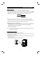
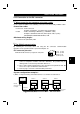
Recommended tightening torque: 0.22 N
⋅
m to 0.25 N
⋅
m
Use a small flat-blade screwdriver (tip thickness: 0.6mm/full length: 3.5mm).
6.5mm ±0.5mm
2