
Instruction manual


160
PARAMETERS
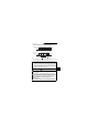
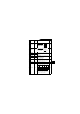
(3) Wiring example
• Pr. 128 = 20
• Pr. 190 = 14
• Pr. 191 = 15
• Pr. 192 = 16
Note:1. The power supply must be selected in accordance with the power
specifications of the detector used.
2. The output signal terminals used depends on the Pr. 190 to Pr. 192 settings.
Power supply
MCCB
Inverter
Forward rotation
Reverse rotation
Setting potentiometer
(Set point setting)
0
(Note 1)
AC1
φ
200/220V 50/60Hz
R (L
1
)
S (L
2
)
T (L
3
)
STF
STR
SD
10
2
5
4
V
W
(Note 2)
SU
RUN
SE
(Process value) 4 to 20mADC
Motor
IM
Pump
P
Upper limit
Lower limit
Limit signal common
For 2-wire
type
Detector
For 3-wire
type
+-
(OUT)
(24V)
(COM)
A
C
Forward rotation output
Reverse rotation output
Forward (reverse)
rotation output
signal common
U
-++
24V
DC power
supply