
Instruction manual


26
INSTALLATION AND WIRING
2.2.3 Wiring of the control circuit
(1) Wiring instructions
1) Terminals SD, SE and 5 are common to the I/O signals. These common terminals must
not be earthed (grounded) to the ground.
Terminals SD and 5 are not isolated. Do not connect terminals SE-5. (Those of the 400V
class are isolated. Avoid connecting the terminal SD and 5 and the terminal SE and 5.)
2) Use shielded or twisted cables for connection to the control circuit terminals and run them
away from the main and power circuits (including the 200V relay sequence circuit).
3) The frequency input signals to the control circuit are micro currents. When contacts
are required, use two or more parallel micro signal contacts or a twin contact to
prevent a contact fault.
4) It is recommended to use the cables of 0.3mm
2
to 0.75mm
2
gauge for connection to
the control circuit terminals.
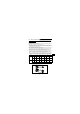
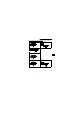
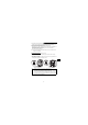
(2) Terminal block layout
In the control circuit of the inverter, the terminals are arranged as shown below:
Terminal screw size: M2.5
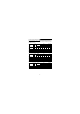
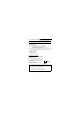
(3) Wiring method
1) For wiring the control circuit, use cables after stripping their sheaths.
Refer to the gauge printed on the inverter and strip the sheaths to the following
dimensions. If the sheath is stripped too much, its cable may be shorted with the
adjoining cable. If the sheath is stripped too little, the cable may come off.
(400V class)(200V class, 100V class)
RH
RM
RL
MRS
RES
SD
PC
SE
RUN
FU
A
B
C
10
2
5
4
SD
STF
STR
SD
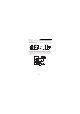
Terminal layout of control circuit
FM
7mm ± 1m
m