
Instruction manual


28
INSTALLATION AND WIRING
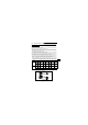
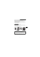
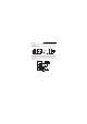
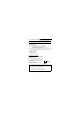
2) Sink logic type
• In this logic, a signal switches on when a current flows out of the corresponding signal
input terminal.
Terminal SD is common to the contact input signals. Terminal SE is common to the
open collector output signals.
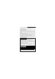
• Use terminal PC as a common terminal, and perform wiring as shown below. (Do not
connect terminal SD of the inverter with terminal 0V of the external power supply.
When using terminals PC-SD as a 24VDC power supply, do not install a power supply
in parallel in the outside of the inverter. Doing so may cause a malfunction due to
undesirable current.)
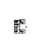
Current
STF
STR
R
R
SD
QX40Inverter
R
R
RUN
SE
TB1
TB17
24VDC
QY40P type transistor
output unit
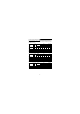
TB1
TB2
TB17
TB18
24VDC
SD
PC
STR
STF
Inverter
24VDC
(SD)
Current flow
Constant
voltage
circuit