
Instruction manual


30
INSTALLATION AND WIRING
2.2.4 Connection to the PU connector
(1) When connecting the operation panel or parameter unit using a cable
Use the option FR-CB2 or the following connector and commercially available
cable:
<Connection cable>
• Connector: RJ45 connector
Example: 5-554720-3, Tyco Electronics Corporation
• Cable: :Cable conforming to EIA568 (e.g. 10BASE-T cable)
Example: SGLPEV-T 0.5mm×4P (Twisted pair cable, 4 pairs),
MITSUBISHI CABLE INDUSTRIES, LTD.
Note: The rear cover and junction adaptor are required since the circuit board is
exposed in the back of the operation panel. Use the FR-E5P option (cover and
adaptor available as a set).
<Maximum wiring length>
• Operation panel: 20m
• Parameter unit (FR-PU04): 20m
(2) For RS-485 communication
With the operation panel disconnected, the PU
connector can be used for communication operation
from a personal computer etc.
When the PU connector is connected with a personal,
FA or other computer by a communication cable, a
user program can run and monitor the inverter or read
and write to the parameters.
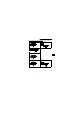
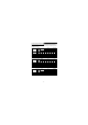
<PU connector pin-outs>
Viewed from the inverter (receptacle side) front
Note: 1. Do not connect the PU connector to a computer's LAN board, FAX modem
socket or telephone modular connector. The product could be damaged
due to differences in electrical specifications.
2. Pins 2) and 8) (P5S) provide power to the operation panel or parameter
unit.
Do not use these pins for RS-485 communication.
3. Refer to page 144 for the communication parameters.
8
)
to 1
)
1) SG
2) P5S
3) RDA
4) SDB
5) SDA
6) RDB
7) SG
8) P5S