MITSUBISHI ELECTRIC FR-E 500 Frequency Inverter Installation Manual FR-E 520S EC FR-E 540 EC Art.-No.
About this Manual The texts, illustrations, diagrams, and examples contained in this manual are only intended as aids to help explain the installation, set-up, and starting of the frequency inverters FR-E 520S EC and FR-E 540 EC. If you have any questions concerning the programming and operation of the equipment described in this manual, please contact your relevant sales office or department (refer to back of cover).
1 Introduction 1.1 General Description . . . . . . . . . . . . . . . . . . . . . . . . . . . . . . . . . . . . . . . . . . . . . . . . .7 2 Specifications 2.1 Model Specifications FR-E 520S EC (1-phase connection). . . . . . . . . . . . . . . . . . . 8 2.2 Model Specifications FR-E 540 EC (3-phase connection) . . . . . . . . . . . . . . . . . . . . 9 2.3 Model Specifications FR-E 500 EC . . . . . . . . . . . . . . . . . . . . . . . . . . . . . . . . . . . .10 3 Appearance and Structure 3.
Safety instructions For qualified staff only This manual is only intended for use by properly trained and qualified electrical technicians who are fully acquainted with automation technology safety standards.
General safety informations and precautions The following safety precautions are intended as a general guideline for using the frequency inverter together with other equipment. These precautions must always be observed in the design, installation and operation of all control systems. P DANGER: 쎲 Observe all safety and accident prevention regulations applicable to your specific application.
Safety warnings In this manual special warnings that are important for the proper and safe use of the products are clearly identified as follows: 6 P DANGER: Personnel health and injury warnings. Failure to observe the precautions described here can result in serious health and injury hazards. E CAUTION: Equipment and property damage warnings. Failure to observe the precautions described here can result in serious damage to the equipment or other property.
Introduction 1 Introduction This Installation Manual includes a brief summary of the main specifications of the FR-E 500 frequency inverters, which should be sufficient to enable experienced users to install and configure the inverter. For further information on the functions and parametrization please refer to the Instruction Manual of the frequency inverter FR-E 500. This Installation Manual is intended exclusively as an installation and setup guide and a brief reference.
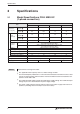
Specifications 2 Specifications 2.1 Model Specifications FR-E 520S EC (1-phase connection) FR-E 520S EC Type Rated motor capacity [kW] Output Rated current [A] 0.4 k 0.75 k 1.5 k 2.2 k 150% Overload capacity 0.75 1.1 2.2 3 200% Overload capacity 0.4 0.75 1.5 2.2 150% Overload capacity 3.6 5 9.6 12 200% Overload capacity 2.5 4 7 10 1.5 2.7 3.8 Rated output capacity [kVA] Overload capacity 0.95 150% of rated motor capacity for 0.5s; 120% for 1min (max.
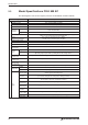
Specifications Model Specifications FR-E 540 EC (3-phase connection) 2.2 FR-E 540 EC Type Rated motor capacity [kW] Output Rated current [A] 0.4 k 0.75 k 1.5 k 2.2 k 3.7 k 5.5 k 7.5 k 150% Overload capacity 0.75 1.1 2.2 3 4 7.5 11 200% Overload capacity 0.4 0.75 1.5 2.2 4 5.5 7.5 150% Overload capacity 1.8 3 4.9 6.7 9.5 14 21 200 % Overload capacity 1.6 (1.4) 2.6 (2.2) 4 (3.8) 6 (5.4) 9.5 (8.7) 12 17 1.2 2.0 3.0 4.6 7.2 9.1 13.
Specifications Model Specifications FR-E 500 EC 2.3 The following datas refer to the frequency inverters FR-E 520S EC und FR-E 540 EC. Type Control method Extended flux vector control with online auto tuning of motor data or V/f control Modulation control Sine evaluated PWM, Soft PWM Carrier frequency 0.7–14.
Specifications Type Description Control inputs Operation functions Output signals Operation status Protection Display option Analog signal Displayed on control panel (FR-PU04/ FR-PA02-02) Additional diplays on control panel FR-PU04 Operating state Alarm display 2 output types (open collector output) can be selected: inverter running, frequency reached, frequency detection, overload warning, zero return detection, output current detection, maximum PID, minimum PID, PID forward run, PID reverse run
Appearance and Structure 3 Appearance and Structure 3.1 Description of the Case Depending on the capacity class the frequency inverter is delivered in two different structural shapes of the case. The following drawings show a structured view of the single case components.
Wiring 4 Wiring 4.1 Overview E CAUTION: The terminals PC-SD of the 24V DC power supply must not be shorted. Otherwise the inverter will be damaged. Motor I> I> I> 3-phase main supply Analog Frequency setting Control inputs (Do not apply an external voltage!) 24V DC Output Reference point for control inputs Start forward Start reverse 1. Multispeed setting 2. Multispeed setting 3.
Wiring 4.2 P E 4.2.1 Wiring of the Main Circuit DANGER: The frequency inverter must always be powered off completely before performing any wiring work. Before starting rewiring or other work after performing operation once, check the voltage with a meter etc. more than 10 minutes after power-off. For some time after power-off, there is a dangerous voltage in the capacitor. CAUTION: The inverter must be grounded using the dedicated ground terminal.
Wiring NOTE It is recommended to use a shielded motor cable in order to reduce cable radiation. 1-phase power supply 3-phase power supply Q1 Q1 FR-E 540 EC FR-E 520 S EC L1 I L1 U L1 I L1 N I N V L2 I L2 V W L3 I L3 W U − − P1 P1 + + PR PR PE PE The maximum wiring length of the motor cable Capacity Classes FR-E 500 0.4 k 0.75 k 1.5 k 2.2 k 3.
Wiring 4.2.2 Main Circuit Terminals Terminal assignment for 1-phase power supply − L1 P1 N + PR U V W Screw size: M4 Screw tightening torque: 1.5Nm Terminal assignment for 3-phase power supply L1 − P1 + PR L2 L3 U V W Screw size: M4 Screw tightening torque: 1.
Wiring 4.3 Wiring of the Control Circuit The following picture shows the arrangement of the terminal for the control circuit of the inverter: RH RM RL MRS RES SD AM PC SE RUN FU POWER ALARM A RH B RM SD C 10 RES 2 SD 5 PC AM 4 SE PC SD SINK Jumper Control logic * * RL MRS SE RUN FU SOURCE - P1 + STF STR SD PR FAN 2 FAN 1 The control signal level can be adjusted with the jumper.
Wiring Setting value specification Analog Signal Terminal Terminal name Description 10 (output voltage 5V DC) Voltage output for potentiometer Output voltage 5V DC Max. output current 10mA. Recommended potentiometer: 1kΩ, 2W linear, multiturn potentiometer 2 Input for frequency setting-value signal The voltage setting value 0–5 (10) V is applied to this terminal. The voltage range is preset to 0–5V. (Parameter 73). The input resistance is 10kΩ; The maximum permitted voltage is 20V.
Wiring E NOTE Output signals Analog AM RS485 Terminal Commun. Signal — Terminal name Analog output Connection of control panel (RS485) Description One of the following monitoring functions can be selected: output frequency, motor current or motor voltage. E.g. a DC voltmeter can be connected. Factory setting of output item: output frequency The max. output voltage is 10V, the max. current is 1mA. Communication operation can be performed through RS485.
Parameter 5 Parameter 5.
Parameter Function Second functions Display functions Automatic restart functions Additional function Operation selection functions Motor constants ParaMeaning meter FR-E 500 EC Default 44 Second acceleration/deceleration time 0–360s / 0–3600s 5s / 10s 45 Second deceleration time 0–360s / 0–3600s / 9999 9999 46 Second torque boost 0–30% / 9999 9999 47 Second V/F (base frequency) 0–400Hz / 9999 9999 48 Second stall prevention operation current 0–500A / 9999 9999 52 Control
Parameter Function PID control Additional functions Current detection Sub functions Additional functions ParaMeaning meter User functions Terminal assignment functions Multi-speed operations Sub functions Stop selection function 22 Default 128 PID action selection 0 / 20 / 21 0 129 PID proportional band 0.1–1000% / 9999 100% 130 PID integral time 0.
Parameter Function Additional functions DeviceNetfunctions Additional function Calibration functions Help functions ParaMeaning meter Setting range 251 Output phase failure protection selection 254 Analog polarity reversible lower limit 338 Default 0/1 1 0–100% / 9999 9999 Operation command write 0/1 0 339 Speed command write 0/1 0 340 Link start mode selection 0/1 0 342 E²PROM write selection 0/1 0 345 DeviceNet address (lower byte) 0–255 63 (0x3F) 346 DeviceN
Protective Functions 6 Protective Functions 6.
Protective Functions Error message Display FR-PU04 Meaning Display FR-PA02-02 Description Remedy A) The integrated brake transistor does not operate properly. B) Possibly, a thermal overload occured. Check the relative operating time of the brake resistor. In case of thermal difficulties use an external brake resistor or an inverter of higher capacity. Br. Cct.
Protective Functions Error message Display FR-PU04 OL oL UFU 26 Meaning Display FR-PA02-02 Description Remedy Overcurrent during acceleration If a current of more than 150% of the rated inverter current flows in the motor, this function stops the increase of the frequency until the overload current reduces to prevent the inve r t e r f r o m r e s u l t i n g i n overcurrent shut-off. When the overload current has reduced below 150%, this function increases the frequency again.
Dimensions 7 Dimensions 7.1 Dimensions of the Frequency Inverters FR-E 520S-0.4 k bis 2.2 k EC and FR-E 540-0.4 k to 3.7 k EC Type A A1 FR-E 520S-0.4 k / 0.75 k EC 136 64 FR-E 520S-1.5 k / 2.2 k EC 156 84 FR-E 540-0.4 k / 0.75 k EC 116 44 FR-E 540-1.5 k bis 3.7 k EC 136 64 5 6 128 150 6 138 6 2x ø5 A1 6 61 11 A 140 NOTE Unit: mm There is no cooling fan in the FR-E 520S-0.4 k/0.75 k-EC and FR-E 540-0.4 k/0.75 k-EC. FR-E 540-5.5 k und 7.
MITSUBISHI ELECTRIC HEADQUARTERS EUROPEAN REPRESENTATIVES EUROPEAN REPRESENTATIVES EUROPEAN REPRESENTATIVES MITSUBISHI ELECTRIC EUROPE EUROPE B.V. German Branch Gothaer Straße 8 D-40880 Ratingen Phone: +49 (0)2102 486-0 Fax: +49 (0)2102 486-1120 e mail: megfamail@meg.mee.com MITSUBISHI ELECTRIC FRANCE EUROPE B.V. French Branch 25, Boulevard des Bouvets F-92741 Nanterre Cedex Phone: +33 1 55 68 55 68 Fax: +33 1 55 68 56 85 e mail: factory.automation@fra.mee.com MITSUBISHI ELECTRIC IRELAND EUROPE B.V.