
Instruction manual
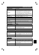
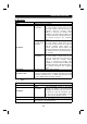
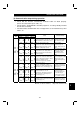
Table Of Contents
- SAFETY INSTRUCTIONS
- CONTENTS
- CHAPTER 1 OUTLINE
- 1.1 Pre-Operation Information
- 1.2 Basic Configuration
- 1.3 Structure
- 1.3.1 Appearance and structure
- 1.3.2 Functions
- 1.3.3 Inverter communication specifications
- 1.3.4 Communication with remote devices
- 1.3.5 Removal and reinstallation of the front cover
- 1.3.6 Removal and reinstallation of the wiring cover
- 1.3.7 Removal and reinstallation of the accessory cover
- 1.3.8 Exploded view
- CHAPTER 2 INSTALLATION AND WIRING
- 2.1 Installation
- 2.2 Wiring
- 2.3 Other Wiring
- 2.3.1 Power supply harmonics
- 2.3.2 Japanese harmonic suppression guideline
- 2.3.3 Inverter-generated noise and reduction techniques
- 2.3.4 Leakage currents and countermeasures
- 2.3.5 Peripheral devices
- 2.3.6 Instructions for compliance with U.S. and Canadian Electrical Codes
- 2.3.7 Instructions for compliance with the European standards
- CHAPTER 3 OPERATION/CONTROL
- 3.1 Inverter Setting
- 3.2 Function Overview
- 3.3 Communication Specifications
- 3.4 Programming Examples
- 3.4.1 Reply code definitions
- 3.4.2 Program example for reading the inverter status
- 3.4.3 Operation mode setting program example
- 3.4.4 Program example for setting the operation commands
- 3.4.5 Program example for monitoring the output frequency
- 3.4.6 Parameter reading program example
- 3.4.7 Parameter writing program example
- 3.4.8 Running frequency setting program example
- 3.4.9 Alarm definition reading program example
- 3.4.10 Inverter resetting program example
- 3.4.11 Instructions
- CHAPTER 4 PARAMETERS
- 4.1 Parameter List
- 4.2 Parameter Function Details
- 4.2.1 Torque boost (Pr. 0, Pr. 46)
- 4.2.2 Output frequency range (Pr. 1, Pr. 2, Pr. 18)
- 4.2.3 Base frequency, base frequency voltage (Pr. 3, Pr. 19, Pr. 47)
- 4.2.4 Multi-speed operation (Pr. 4, Pr. 5, Pr. 6, Pr. 24 to Pr. 27, Pr. 232 to Pr. 239)
- 4.2.5 Acceleration time (Pr. 7, Pr. 8, Pr. 20, Pr. 21, Pr. 44, Pr. 45)
- 4.2.6 Electronic overcurrent protection (Pr. 9, Pr. 48)
- 4.2.7 DC injection brake (Pr. 10 to Pr. 12)
- 4.2.8 Starting frequency (Pr. 13)
- 4.2.9 Load pattern selection (Pr. 14)
- 4.2.10 Stall prevention (Pr. 22, Pr. 23, Pr. 66)
- 4.2.11 Acceleration/deceleration pattern (Pr. 29)
- 4.2.12 Regenerative brake duty (Pr. 30, Pr. 70)
- 4.2.13 Frequency jump (Pr. 31 to Pr. 36)
- 4.2.14 Speed display (Pr. 37)
- 4.2.15 Up-to-frequency sensitivity (Pr. 41)
- 4.2.16 Output frequency detection (Pr. 42, Pr. 43)
- 4.2.17 Monitor display (Pr. 52)
- 4.2.18 Automatic restart after instantaneous power failure (Pr. 57, Pr. 58)
- 4.2.19 Shortest acceleration/deceleration mode (Pr. 60 to Pr.63)
- 4.2.20 Retry function (Pr. 65, Pr. 67 to Pr. 69)
- 4.2.21 Applied motor (Pr. 71)
- 4.2.22 PWM carrier frequency (Pr. 72, Pr. 240)
- 4.2.23 Reset selection/disconnected PU detection/PU stop selection (Pr. 75)
- 4.2.24 Parameter write disable selection (Pr. 77)
- 4.2.25 Reverse rotation prevention selection (Pr. 78)
- 4.2.26 Operation mode selection (Pr. 79)
- 4.2.27 General-purpose magnetic flux vector control selection (Pr. 80)
- 4.2.28 Offline auto tuning function (Pr. 82 to Pr. 84, Pr. 90, Pr. 96)
- 4.2.29 Computer link operation (Pr. 117 to Pr. 124)
- 4.2.30 Output current detection function (Pr. 150, Pr. 151)
- 4.2.31 Zero current detection (Pr. 152, Pr. 153)
- 4.2.32 Stall prevention (Pr. 156)
- 4.2.33 User group selection (Pr. 160, Pr. 173 to Pr. 176)
- 4.2.34 Actual operation hour meter clear (Pr. 171)
- 4.2.35 Input terminal (remote output) function selection (Pr. 180 to Pr. 183)
- 4.2.36 Output (remote input) function selection (Pr. 190 to Pr. 192)
- 4.2.37 Cooling fan operation selection (Pr. 244)
- 4.2.38 Slip compensation (Pr. 245 to Pr. 247)
- 4.2.39 Ground fault detection at start (Pr. 249)
- 4.2.40 Stop selection (Pr. 250)
- 4. 2. 41 Communication error "E.OPT" operation selection (Pr. 500 to Pr. 502)
- CHAPTER 5 PROTECTIVE FUNCTIONS
- 5.1 Errors (Alarms)
- 5.2 Troubleshooting
- 5.2.1 Motor remains stopped
- 5.2.2 Motor rotates in opposite direction
- 5.2.3 Speed greatly differs from the setting
- 5.2.4 Acceleration/deceleration is not smooth
- 5.2.5 Motor current is large
- 5.2.6 Speed does not increase
- 5.2.7 Speed varies during operation
- 5.2.8 Operation mode unswitched to CC-Link operation mode
- 5.2.9 Inverter unstarted in CC-Link operation mode
- 5.2.10 Parameter write cannot be performed
- 5.3 Precautions for Maintenance and Inspection
- CHAPTER 6 SPECIFICATIONS
- APPENDIX
- REVISIONS

PROTECTIVE FUNCTIONS
147
FR-PU04 Indication
PS
Name
PU stop
Description
A stop made by pressing the
STOP
RESET
key of the PU has been
set in Pr. 75 "PU stop selection".
Check point
Check for a stop made by pressing the
STOP
RESET
key of the
operation panel during external operation.
Corrective action
Refer to page 102.
5.1.3 To know the operating status at the occurrence of alarm
When any alarm has occurred, the ALARM lamp is lit. When the parameter unit
(FR-PU04) is used, the PU display automatically switches to the indication of the
corresponding protective function (error) and shows the error definition and output
frequency.
5