
Instruction manual
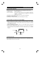

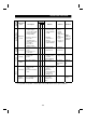


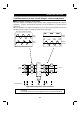
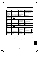
Table Of Contents
- SAFETY INSTRUCTIONS
- CONTENTS
- CHAPTER 1 OUTLINE
- 1.1 Pre-Operation Information
- 1.2 Basic Configuration
- 1.3 Structure
- 1.3.1 Appearance and structure
- 1.3.2 Functions
- 1.3.3 Inverter communication specifications
- 1.3.4 Communication with remote devices
- 1.3.5 Removal and reinstallation of the front cover
- 1.3.6 Removal and reinstallation of the wiring cover
- 1.3.7 Removal and reinstallation of the accessory cover
- 1.3.8 Exploded view
- CHAPTER 2 INSTALLATION AND WIRING
- 2.1 Installation
- 2.2 Wiring
- 2.3 Other Wiring
- 2.3.1 Power supply harmonics
- 2.3.2 Japanese harmonic suppression guideline
- 2.3.3 Inverter-generated noise and reduction techniques
- 2.3.4 Leakage currents and countermeasures
- 2.3.5 Peripheral devices
- 2.3.6 Instructions for compliance with U.S. and Canadian Electrical Codes
- 2.3.7 Instructions for compliance with the European standards
- CHAPTER 3 OPERATION/CONTROL
- 3.1 Inverter Setting
- 3.2 Function Overview
- 3.3 Communication Specifications
- 3.4 Programming Examples
- 3.4.1 Reply code definitions
- 3.4.2 Program example for reading the inverter status
- 3.4.3 Operation mode setting program example
- 3.4.4 Program example for setting the operation commands
- 3.4.5 Program example for monitoring the output frequency
- 3.4.6 Parameter reading program example
- 3.4.7 Parameter writing program example
- 3.4.8 Running frequency setting program example
- 3.4.9 Alarm definition reading program example
- 3.4.10 Inverter resetting program example
- 3.4.11 Instructions
- CHAPTER 4 PARAMETERS
- 4.1 Parameter List
- 4.2 Parameter Function Details
- 4.2.1 Torque boost (Pr. 0, Pr. 46)
- 4.2.2 Output frequency range (Pr. 1, Pr. 2, Pr. 18)
- 4.2.3 Base frequency, base frequency voltage (Pr. 3, Pr. 19, Pr. 47)
- 4.2.4 Multi-speed operation (Pr. 4, Pr. 5, Pr. 6, Pr. 24 to Pr. 27, Pr. 232 to Pr. 239)
- 4.2.5 Acceleration time (Pr. 7, Pr. 8, Pr. 20, Pr. 21, Pr. 44, Pr. 45)
- 4.2.6 Electronic overcurrent protection (Pr. 9, Pr. 48)
- 4.2.7 DC injection brake (Pr. 10 to Pr. 12)
- 4.2.8 Starting frequency (Pr. 13)
- 4.2.9 Load pattern selection (Pr. 14)
- 4.2.10 Stall prevention (Pr. 22, Pr. 23, Pr. 66)
- 4.2.11 Acceleration/deceleration pattern (Pr. 29)
- 4.2.12 Regenerative brake duty (Pr. 30, Pr. 70)
- 4.2.13 Frequency jump (Pr. 31 to Pr. 36)
- 4.2.14 Speed display (Pr. 37)
- 4.2.15 Up-to-frequency sensitivity (Pr. 41)
- 4.2.16 Output frequency detection (Pr. 42, Pr. 43)
- 4.2.17 Monitor display (Pr. 52)
- 4.2.18 Automatic restart after instantaneous power failure (Pr. 57, Pr. 58)
- 4.2.19 Shortest acceleration/deceleration mode (Pr. 60 to Pr.63)
- 4.2.20 Retry function (Pr. 65, Pr. 67 to Pr. 69)
- 4.2.21 Applied motor (Pr. 71)
- 4.2.22 PWM carrier frequency (Pr. 72, Pr. 240)
- 4.2.23 Reset selection/disconnected PU detection/PU stop selection (Pr. 75)
- 4.2.24 Parameter write disable selection (Pr. 77)
- 4.2.25 Reverse rotation prevention selection (Pr. 78)
- 4.2.26 Operation mode selection (Pr. 79)
- 4.2.27 General-purpose magnetic flux vector control selection (Pr. 80)
- 4.2.28 Offline auto tuning function (Pr. 82 to Pr. 84, Pr. 90, Pr. 96)
- 4.2.29 Computer link operation (Pr. 117 to Pr. 124)
- 4.2.30 Output current detection function (Pr. 150, Pr. 151)
- 4.2.31 Zero current detection (Pr. 152, Pr. 153)
- 4.2.32 Stall prevention (Pr. 156)
- 4.2.33 User group selection (Pr. 160, Pr. 173 to Pr. 176)
- 4.2.34 Actual operation hour meter clear (Pr. 171)
- 4.2.35 Input terminal (remote output) function selection (Pr. 180 to Pr. 183)
- 4.2.36 Output (remote input) function selection (Pr. 190 to Pr. 192)
- 4.2.37 Cooling fan operation selection (Pr. 244)
- 4.2.38 Slip compensation (Pr. 245 to Pr. 247)
- 4.2.39 Ground fault detection at start (Pr. 249)
- 4.2.40 Stop selection (Pr. 250)
- 4. 2. 41 Communication error "E.OPT" operation selection (Pr. 500 to Pr. 502)
- CHAPTER 5 PROTECTIVE FUNCTIONS
- 5.1 Errors (Alarms)
- 5.2 Troubleshooting
- 5.2.1 Motor remains stopped
- 5.2.2 Motor rotates in opposite direction
- 5.2.3 Speed greatly differs from the setting
- 5.2.4 Acceleration/deceleration is not smooth
- 5.2.5 Motor current is large
- 5.2.6 Speed does not increase
- 5.2.7 Speed varies during operation
- 5.2.8 Operation mode unswitched to CC-Link operation mode
- 5.2.9 Inverter unstarted in CC-Link operation mode
- 5.2.10 Parameter write cannot be performed
- 5.3 Precautions for Maintenance and Inspection
- CHAPTER 6 SPECIFICATIONS
- APPENDIX
- REVISIONS

PROTECTIVE FUNCTIONS
157
5.3.6 Daily and Periodic Inspection
Interval
Periodic*
Area of
Inspection
Inspection
Item
Description
Daily
1 year
2 years
Method Criterion
Instrument
Surrounding
environment
Check ambient
temperature, humidity,
dust, dirt, etc.
#
Refer to page 10.
Ambient
temperature:
(constant
torque) -10
°
C to
+50
°
C, non-freezing.
(Variable torque)
-10
°
C to +40
°
C
non-freezing
Ambient
humidity: 90%
or less, non-
condensing.
Thermometer,
hygrometer,
recorder
Overall unit
Check for unusual
vibration and noise.
#
Visual and auditory
checks.
No fault.
General
Power
supply
voltage
Check that main
circuit voltage is
normal.
#
Measure voltage
across inverter
terminals R-S-T
(L1-L2-L3).
Within
permissible AC
(DC) voltage
fluctuation
(Refer to page
164)
Meter,
digital
multimeter
General
(1) Check with megger
(across main circuit
terminals and
ground terminal).
(2) Check for loose
screws and bolts.
(3) Check for overheat
on each part.
(4) Clean.
#
#
#
#
(1) Disconnect all
cables from
inverter and
measure across
terminals R(L1),
S(L2), T(L3), U,
V, W and ground
terminal with
megger.
(2) Retighten.
(3) Visual check.
(1) 5M
Ω
or
more.
(2), (3) No fault. 500VDC
class
megger
Conductors,
cables
(1) Check conductors
for distortion.
(2)
Check cable sheaths
for breakage.
#
#
(1), (2) Visual check. (1), (2) No fault.
Terminal
block
Check for damage.
#
Visual check No fault
Inverter
module
Converter
module
Check resistance
across terminals.
#
Disconnect cables
from inverter and
measure across
terminals R, S, T-P, N
(L
1
, L
2
, L
3
- +,
−
−−
−
), and
across U, V, W-P(+),
N(-) with a meter
with a 100
Ω
range.
Refer to page
159.
Analog
meter
Main circuit
Smoothing
capacitor
(1) Check for liquid
leakage.
(2) Check for safety
valve projection
and bulge.
(3) Measure
electrostatic
capacity.
#
#
#
(1), (2) Visual check.
(3) Measure with
capacity meter.
(1), (2) No fault.
(3) 85% or more
of rated
capacity.
Capacity
meter
5