
Instruction manual
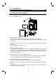
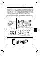
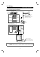
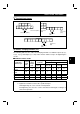
Table Of Contents
- SAFETY INSTRUCTIONS
- CONTENTS
- CHAPTER 1 OUTLINE
- 1.1 Pre-Operation Information
- 1.2 Basic Configuration
- 1.3 Structure
- 1.3.1 Appearance and structure
- 1.3.2 Functions
- 1.3.3 Inverter communication specifications
- 1.3.4 Communication with remote devices
- 1.3.5 Removal and reinstallation of the front cover
- 1.3.6 Removal and reinstallation of the wiring cover
- 1.3.7 Removal and reinstallation of the accessory cover
- 1.3.8 Exploded view
- CHAPTER 2 INSTALLATION AND WIRING
- 2.1 Installation
- 2.2 Wiring
- 2.3 Other Wiring
- 2.3.1 Power supply harmonics
- 2.3.2 Japanese harmonic suppression guideline
- 2.3.3 Inverter-generated noise and reduction techniques
- 2.3.4 Leakage currents and countermeasures
- 2.3.5 Peripheral devices
- 2.3.6 Instructions for compliance with U.S. and Canadian Electrical Codes
- 2.3.7 Instructions for compliance with the European standards
- CHAPTER 3 OPERATION/CONTROL
- 3.1 Inverter Setting
- 3.2 Function Overview
- 3.3 Communication Specifications
- 3.4 Programming Examples
- 3.4.1 Reply code definitions
- 3.4.2 Program example for reading the inverter status
- 3.4.3 Operation mode setting program example
- 3.4.4 Program example for setting the operation commands
- 3.4.5 Program example for monitoring the output frequency
- 3.4.6 Parameter reading program example
- 3.4.7 Parameter writing program example
- 3.4.8 Running frequency setting program example
- 3.4.9 Alarm definition reading program example
- 3.4.10 Inverter resetting program example
- 3.4.11 Instructions
- CHAPTER 4 PARAMETERS
- 4.1 Parameter List
- 4.2 Parameter Function Details
- 4.2.1 Torque boost (Pr. 0, Pr. 46)
- 4.2.2 Output frequency range (Pr. 1, Pr. 2, Pr. 18)
- 4.2.3 Base frequency, base frequency voltage (Pr. 3, Pr. 19, Pr. 47)
- 4.2.4 Multi-speed operation (Pr. 4, Pr. 5, Pr. 6, Pr. 24 to Pr. 27, Pr. 232 to Pr. 239)
- 4.2.5 Acceleration time (Pr. 7, Pr. 8, Pr. 20, Pr. 21, Pr. 44, Pr. 45)
- 4.2.6 Electronic overcurrent protection (Pr. 9, Pr. 48)
- 4.2.7 DC injection brake (Pr. 10 to Pr. 12)
- 4.2.8 Starting frequency (Pr. 13)
- 4.2.9 Load pattern selection (Pr. 14)
- 4.2.10 Stall prevention (Pr. 22, Pr. 23, Pr. 66)
- 4.2.11 Acceleration/deceleration pattern (Pr. 29)
- 4.2.12 Regenerative brake duty (Pr. 30, Pr. 70)
- 4.2.13 Frequency jump (Pr. 31 to Pr. 36)
- 4.2.14 Speed display (Pr. 37)
- 4.2.15 Up-to-frequency sensitivity (Pr. 41)
- 4.2.16 Output frequency detection (Pr. 42, Pr. 43)
- 4.2.17 Monitor display (Pr. 52)
- 4.2.18 Automatic restart after instantaneous power failure (Pr. 57, Pr. 58)
- 4.2.19 Shortest acceleration/deceleration mode (Pr. 60 to Pr.63)
- 4.2.20 Retry function (Pr. 65, Pr. 67 to Pr. 69)
- 4.2.21 Applied motor (Pr. 71)
- 4.2.22 PWM carrier frequency (Pr. 72, Pr. 240)
- 4.2.23 Reset selection/disconnected PU detection/PU stop selection (Pr. 75)
- 4.2.24 Parameter write disable selection (Pr. 77)
- 4.2.25 Reverse rotation prevention selection (Pr. 78)
- 4.2.26 Operation mode selection (Pr. 79)
- 4.2.27 General-purpose magnetic flux vector control selection (Pr. 80)
- 4.2.28 Offline auto tuning function (Pr. 82 to Pr. 84, Pr. 90, Pr. 96)
- 4.2.29 Computer link operation (Pr. 117 to Pr. 124)
- 4.2.30 Output current detection function (Pr. 150, Pr. 151)
- 4.2.31 Zero current detection (Pr. 152, Pr. 153)
- 4.2.32 Stall prevention (Pr. 156)
- 4.2.33 User group selection (Pr. 160, Pr. 173 to Pr. 176)
- 4.2.34 Actual operation hour meter clear (Pr. 171)
- 4.2.35 Input terminal (remote output) function selection (Pr. 180 to Pr. 183)
- 4.2.36 Output (remote input) function selection (Pr. 190 to Pr. 192)
- 4.2.37 Cooling fan operation selection (Pr. 244)
- 4.2.38 Slip compensation (Pr. 245 to Pr. 247)
- 4.2.39 Ground fault detection at start (Pr. 249)
- 4.2.40 Stop selection (Pr. 250)
- 4. 2. 41 Communication error "E.OPT" operation selection (Pr. 500 to Pr. 502)
- CHAPTER 5 PROTECTIVE FUNCTIONS
- 5.1 Errors (Alarms)
- 5.2 Troubleshooting
- 5.2.1 Motor remains stopped
- 5.2.2 Motor rotates in opposite direction
- 5.2.3 Speed greatly differs from the setting
- 5.2.4 Acceleration/deceleration is not smooth
- 5.2.5 Motor current is large
- 5.2.6 Speed does not increase
- 5.2.7 Speed varies during operation
- 5.2.8 Operation mode unswitched to CC-Link operation mode
- 5.2.9 Inverter unstarted in CC-Link operation mode
- 5.2.10 Parameter write cannot be performed
- 5.3 Precautions for Maintenance and Inspection
- CHAPTER 6 SPECIFICATIONS
- APPENDIX
- REVISIONS

INSTALLATION AND WIRING
11
7) Note the cooling method when the inverter is installed in an enclosure.
When two or more inverters are installed or a ventilation fan is mounted in an
enclosure, the inverters and ventilation fan must be installed in proper positions with
extreme care taken to keep the ambient temperatures of the inverters with the
permissible values. If they are installed in improper positions, the ambient
temperatures of the inverters will rise and ventilation effect will be reduced.
8) Install the inverter on an installation surface securely and vertically with screws or
bolts.
3) Note on ambient
temperatures
Measurement
position
Measurement
p
osition
5
cm
5cm
5
cm
FR-E500
4) Clearances around the inverter
FR-E500
10cm
or more
10cm
or more
Leave sufficient
clearances above
and under the
inverter to ensure
adequate ventilation.
Cooling fan
built in the
inverter
1cm or
more*
1cm or
more*
Cooling air
*5cm or more for 5.5K and 7.5K
These clearances are also necessar
y
for chan
g
in
g
the coolin
g
fan.
7) For installation in an enclosure
Inverter
V
entilation
f
an
(Correct example) (Incorrect example)
Position of Ventilation Fan
Inverter
Built-in cooling fan
(Correct example)
Inverter
Inverter
When more than one inverter is contained
(Incorrect example)
Inverter
Inverter
8) Vertical mounting
2