
Instruction manual
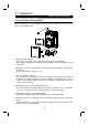
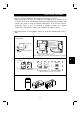
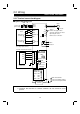
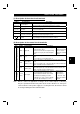
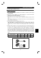
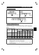
Table Of Contents
- SAFETY INSTRUCTIONS
- CONTENTS
- CHAPTER 1 OUTLINE
- 1.1 Pre-Operation Information
- 1.2 Basic Configuration
- 1.3 Structure
- 1.3.1 Appearance and structure
- 1.3.2 Functions
- 1.3.3 Inverter communication specifications
- 1.3.4 Communication with remote devices
- 1.3.5 Removal and reinstallation of the front cover
- 1.3.6 Removal and reinstallation of the wiring cover
- 1.3.7 Removal and reinstallation of the accessory cover
- 1.3.8 Exploded view
- CHAPTER 2 INSTALLATION AND WIRING
- 2.1 Installation
- 2.2 Wiring
- 2.3 Other Wiring
- 2.3.1 Power supply harmonics
- 2.3.2 Japanese harmonic suppression guideline
- 2.3.3 Inverter-generated noise and reduction techniques
- 2.3.4 Leakage currents and countermeasures
- 2.3.5 Peripheral devices
- 2.3.6 Instructions for compliance with U.S. and Canadian Electrical Codes
- 2.3.7 Instructions for compliance with the European standards
- CHAPTER 3 OPERATION/CONTROL
- 3.1 Inverter Setting
- 3.2 Function Overview
- 3.3 Communication Specifications
- 3.4 Programming Examples
- 3.4.1 Reply code definitions
- 3.4.2 Program example for reading the inverter status
- 3.4.3 Operation mode setting program example
- 3.4.4 Program example for setting the operation commands
- 3.4.5 Program example for monitoring the output frequency
- 3.4.6 Parameter reading program example
- 3.4.7 Parameter writing program example
- 3.4.8 Running frequency setting program example
- 3.4.9 Alarm definition reading program example
- 3.4.10 Inverter resetting program example
- 3.4.11 Instructions
- CHAPTER 4 PARAMETERS
- 4.1 Parameter List
- 4.2 Parameter Function Details
- 4.2.1 Torque boost (Pr. 0, Pr. 46)
- 4.2.2 Output frequency range (Pr. 1, Pr. 2, Pr. 18)
- 4.2.3 Base frequency, base frequency voltage (Pr. 3, Pr. 19, Pr. 47)
- 4.2.4 Multi-speed operation (Pr. 4, Pr. 5, Pr. 6, Pr. 24 to Pr. 27, Pr. 232 to Pr. 239)
- 4.2.5 Acceleration time (Pr. 7, Pr. 8, Pr. 20, Pr. 21, Pr. 44, Pr. 45)
- 4.2.6 Electronic overcurrent protection (Pr. 9, Pr. 48)
- 4.2.7 DC injection brake (Pr. 10 to Pr. 12)
- 4.2.8 Starting frequency (Pr. 13)
- 4.2.9 Load pattern selection (Pr. 14)
- 4.2.10 Stall prevention (Pr. 22, Pr. 23, Pr. 66)
- 4.2.11 Acceleration/deceleration pattern (Pr. 29)
- 4.2.12 Regenerative brake duty (Pr. 30, Pr. 70)
- 4.2.13 Frequency jump (Pr. 31 to Pr. 36)
- 4.2.14 Speed display (Pr. 37)
- 4.2.15 Up-to-frequency sensitivity (Pr. 41)
- 4.2.16 Output frequency detection (Pr. 42, Pr. 43)
- 4.2.17 Monitor display (Pr. 52)
- 4.2.18 Automatic restart after instantaneous power failure (Pr. 57, Pr. 58)
- 4.2.19 Shortest acceleration/deceleration mode (Pr. 60 to Pr.63)
- 4.2.20 Retry function (Pr. 65, Pr. 67 to Pr. 69)
- 4.2.21 Applied motor (Pr. 71)
- 4.2.22 PWM carrier frequency (Pr. 72, Pr. 240)
- 4.2.23 Reset selection/disconnected PU detection/PU stop selection (Pr. 75)
- 4.2.24 Parameter write disable selection (Pr. 77)
- 4.2.25 Reverse rotation prevention selection (Pr. 78)
- 4.2.26 Operation mode selection (Pr. 79)
- 4.2.27 General-purpose magnetic flux vector control selection (Pr. 80)
- 4.2.28 Offline auto tuning function (Pr. 82 to Pr. 84, Pr. 90, Pr. 96)
- 4.2.29 Computer link operation (Pr. 117 to Pr. 124)
- 4.2.30 Output current detection function (Pr. 150, Pr. 151)
- 4.2.31 Zero current detection (Pr. 152, Pr. 153)
- 4.2.32 Stall prevention (Pr. 156)
- 4.2.33 User group selection (Pr. 160, Pr. 173 to Pr. 176)
- 4.2.34 Actual operation hour meter clear (Pr. 171)
- 4.2.35 Input terminal (remote output) function selection (Pr. 180 to Pr. 183)
- 4.2.36 Output (remote input) function selection (Pr. 190 to Pr. 192)
- 4.2.37 Cooling fan operation selection (Pr. 244)
- 4.2.38 Slip compensation (Pr. 245 to Pr. 247)
- 4.2.39 Ground fault detection at start (Pr. 249)
- 4.2.40 Stop selection (Pr. 250)
- 4. 2. 41 Communication error "E.OPT" operation selection (Pr. 500 to Pr. 502)
- CHAPTER 5 PROTECTIVE FUNCTIONS
- 5.1 Errors (Alarms)
- 5.2 Troubleshooting
- 5.2.1 Motor remains stopped
- 5.2.2 Motor rotates in opposite direction
- 5.2.3 Speed greatly differs from the setting
- 5.2.4 Acceleration/deceleration is not smooth
- 5.2.5 Motor current is large
- 5.2.6 Speed does not increase
- 5.2.7 Speed varies during operation
- 5.2.8 Operation mode unswitched to CC-Link operation mode
- 5.2.9 Inverter unstarted in CC-Link operation mode
- 5.2.10 Parameter write cannot be performed
- 5.3 Precautions for Maintenance and Inspection
- CHAPTER 6 SPECIFICATIONS
- APPENDIX
- REVISIONS

INSTALLATION AND WIRING
16
6) Connect only the recommended optional brake resistor between the terminals
P-PR (+-PR). Keep terminals P-PR (+-PR) of 0.1K or 0.2K open.
These terminals must not be shorted.
0.1K and 0.2K do not accept the brake resistor. Keep terminals P-PR (+-PR) open.
Also, never short these terminals.
7) Electromagnetic wave interference
The input/output (main circuit) of the inverter includes harmonic components, which
may interfere with the communication devices (such as AM radios) used near the
inverter. In this case, install the FR-BIF optional radio noise filter (for use in the input
side only) or FR-BSF01 or FR-BLF line noise filter to minimize interference.
8) Do not install a power capacitor, surge suppressor or radio noise filter (FR-BIF
option) in the output side of the inverter.
This will cause the inverter to trip or the capacitor and surge suppressor to be
damaged. If any of the above devices are installed, immediately remove them.
(When using the FR-BIF radio noise filter with a single-phase power supply, connect
it to the input side of the inverter after isolating the T phase securely.)
9) When rewiring after operation, make sure that the POWER lamp has gone off, and
when more than 10 minutes has elapsed after power-off, check with a meter etc.
that the voltage is zero. After that, start rewiring work. For some time after power-off,
there is a dangerous voltage in the capacitor.
Notes on Grounding
"
Leakage currents flow in the inverter. To prevent an electric shock, the inverter
and motor must be grounded.
"
Use the dedicated ground terminal to ground the inverter. (Do not use the screw
in the case, chassis, etc.)
"
The ground cable should be as thick as possible. Its gauge should be equal to or
larger than those indicated in the following table. The grounding point should be
as near as possible to the inverter to minimize the ground cable length.
"
Ground the motor on the inverter side using one wire of the 4-core cable.
(Unit: mm
2
)
Ground Cable Gauge
Motor Capacity
200V class
2.2kW or less
2
3.7kW
3.5
5.5kW, 7.5kW
5.5