
Instruction manual
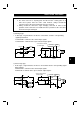
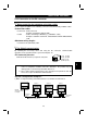
Table Of Contents
- SAFETY INSTRUCTIONS
- CONTENTS
- CHAPTER 1 OUTLINE
- 1.1 Pre-Operation Information
- 1.2 Basic Configuration
- 1.3 Structure
- 1.3.1 Appearance and structure
- 1.3.2 Functions
- 1.3.3 Inverter communication specifications
- 1.3.4 Communication with remote devices
- 1.3.5 Removal and reinstallation of the front cover
- 1.3.6 Removal and reinstallation of the wiring cover
- 1.3.7 Removal and reinstallation of the accessory cover
- 1.3.8 Exploded view
- CHAPTER 2 INSTALLATION AND WIRING
- 2.1 Installation
- 2.2 Wiring
- 2.3 Other Wiring
- 2.3.1 Power supply harmonics
- 2.3.2 Japanese harmonic suppression guideline
- 2.3.3 Inverter-generated noise and reduction techniques
- 2.3.4 Leakage currents and countermeasures
- 2.3.5 Peripheral devices
- 2.3.6 Instructions for compliance with U.S. and Canadian Electrical Codes
- 2.3.7 Instructions for compliance with the European standards
- CHAPTER 3 OPERATION/CONTROL
- 3.1 Inverter Setting
- 3.2 Function Overview
- 3.3 Communication Specifications
- 3.4 Programming Examples
- 3.4.1 Reply code definitions
- 3.4.2 Program example for reading the inverter status
- 3.4.3 Operation mode setting program example
- 3.4.4 Program example for setting the operation commands
- 3.4.5 Program example for monitoring the output frequency
- 3.4.6 Parameter reading program example
- 3.4.7 Parameter writing program example
- 3.4.8 Running frequency setting program example
- 3.4.9 Alarm definition reading program example
- 3.4.10 Inverter resetting program example
- 3.4.11 Instructions
- CHAPTER 4 PARAMETERS
- 4.1 Parameter List
- 4.2 Parameter Function Details
- 4.2.1 Torque boost (Pr. 0, Pr. 46)
- 4.2.2 Output frequency range (Pr. 1, Pr. 2, Pr. 18)
- 4.2.3 Base frequency, base frequency voltage (Pr. 3, Pr. 19, Pr. 47)
- 4.2.4 Multi-speed operation (Pr. 4, Pr. 5, Pr. 6, Pr. 24 to Pr. 27, Pr. 232 to Pr. 239)
- 4.2.5 Acceleration time (Pr. 7, Pr. 8, Pr. 20, Pr. 21, Pr. 44, Pr. 45)
- 4.2.6 Electronic overcurrent protection (Pr. 9, Pr. 48)
- 4.2.7 DC injection brake (Pr. 10 to Pr. 12)
- 4.2.8 Starting frequency (Pr. 13)
- 4.2.9 Load pattern selection (Pr. 14)
- 4.2.10 Stall prevention (Pr. 22, Pr. 23, Pr. 66)
- 4.2.11 Acceleration/deceleration pattern (Pr. 29)
- 4.2.12 Regenerative brake duty (Pr. 30, Pr. 70)
- 4.2.13 Frequency jump (Pr. 31 to Pr. 36)
- 4.2.14 Speed display (Pr. 37)
- 4.2.15 Up-to-frequency sensitivity (Pr. 41)
- 4.2.16 Output frequency detection (Pr. 42, Pr. 43)
- 4.2.17 Monitor display (Pr. 52)
- 4.2.18 Automatic restart after instantaneous power failure (Pr. 57, Pr. 58)
- 4.2.19 Shortest acceleration/deceleration mode (Pr. 60 to Pr.63)
- 4.2.20 Retry function (Pr. 65, Pr. 67 to Pr. 69)
- 4.2.21 Applied motor (Pr. 71)
- 4.2.22 PWM carrier frequency (Pr. 72, Pr. 240)
- 4.2.23 Reset selection/disconnected PU detection/PU stop selection (Pr. 75)
- 4.2.24 Parameter write disable selection (Pr. 77)
- 4.2.25 Reverse rotation prevention selection (Pr. 78)
- 4.2.26 Operation mode selection (Pr. 79)
- 4.2.27 General-purpose magnetic flux vector control selection (Pr. 80)
- 4.2.28 Offline auto tuning function (Pr. 82 to Pr. 84, Pr. 90, Pr. 96)
- 4.2.29 Computer link operation (Pr. 117 to Pr. 124)
- 4.2.30 Output current detection function (Pr. 150, Pr. 151)
- 4.2.31 Zero current detection (Pr. 152, Pr. 153)
- 4.2.32 Stall prevention (Pr. 156)
- 4.2.33 User group selection (Pr. 160, Pr. 173 to Pr. 176)
- 4.2.34 Actual operation hour meter clear (Pr. 171)
- 4.2.35 Input terminal (remote output) function selection (Pr. 180 to Pr. 183)
- 4.2.36 Output (remote input) function selection (Pr. 190 to Pr. 192)
- 4.2.37 Cooling fan operation selection (Pr. 244)
- 4.2.38 Slip compensation (Pr. 245 to Pr. 247)
- 4.2.39 Ground fault detection at start (Pr. 249)
- 4.2.40 Stop selection (Pr. 250)
- 4. 2. 41 Communication error "E.OPT" operation selection (Pr. 500 to Pr. 502)
- CHAPTER 5 PROTECTIVE FUNCTIONS
- 5.1 Errors (Alarms)
- 5.2 Troubleshooting
- 5.2.1 Motor remains stopped
- 5.2.2 Motor rotates in opposite direction
- 5.2.3 Speed greatly differs from the setting
- 5.2.4 Acceleration/deceleration is not smooth
- 5.2.5 Motor current is large
- 5.2.6 Speed does not increase
- 5.2.7 Speed varies during operation
- 5.2.8 Operation mode unswitched to CC-Link operation mode
- 5.2.9 Inverter unstarted in CC-Link operation mode
- 5.2.10 Parameter write cannot be performed
- 5.3 Precautions for Maintenance and Inspection
- CHAPTER 6 SPECIFICATIONS
- APPENDIX
- REVISIONS
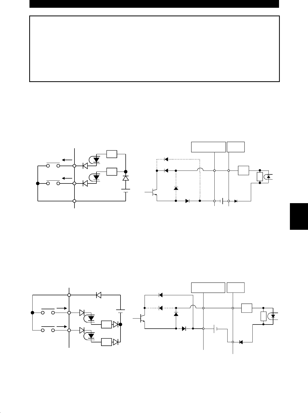
INSTALLATION AND WIRING
21
Note:1. Make sure that the front cover has been installed securely.
2. The front cover has a capacity plate and the inverter a rating plate on it.
Since these plates have the same serial numbers, always reinstall the
removed cover to the inverter from where it was removed.
3. Always install the sink-source logic changing connector in either of the
positions. If two connectors are installed in these positions at the same time,
the inverter may be damaged.
2) Sink logic type
!
In this logic, a signal switches on when a current flows out of the corresponding
signal input terminal.
Terminal SD is common to the contact input signals.
Terminal SE is common to the open collector output signals.
R
R
Current
MRS
RES
SD
AX40
SE
RUN
24VDC
R
1
9
R
• Current flow related
to RUN signal
Inverter
3) Source logic type
!
In this logic, a signal switches on when a current flows into the corresponding signal
input terminal.
Terminal P24 is common to the contact input signals.
Terminal SE is common to the open collector output signals.
R
R
Current
RES
MRS
P24
AX80
24VDC
RUN
SE
1
9
R
R
• Current flow related
to RUN signal
Inverter
2