VARIABLE FREQUENCY DRIVES E500 SERIES EXPANSIVE FUNCTIONALITY IN A C OMPACT PACKAGE
POWERFUL Get a high torque (150%) at speeds as low as 1Hz A regenerative braking resistor can be connected (0.4K or more) The high response current limit function helps provide safety Now with an even higher output current rating Mitsubishi’s New E500 Series Offers Three Great Values. SIMPLE Easy to operate. The control panel now has a frequency setting knob as standard equipment. Easy to maintain. Easy access make the cooling fan easy to replace. Wiring is simple.
Contents Features 3 Networks 6 Model Configurations 7 Standard Specifications 8 External Dimension Diagrams and Terminal Layouts 10 Terminal Connection Diagram 12 Description of Terminal Specifications 13 Operation 14 List of Parameters 15 Description of Parameters 18 Protective Functions 29 Connection Examples 30 Peripherals 32 Optional Equipment 34 Only 85% the volume of a Mitsubishi FREQROLU100 (for FR-E520-0.2K).
Features Advanced Mitsubishi Technology Creates a Winner Highly Cost-Effective and Very Powerful ■ High Torque (150 %) at Speeds as Low as 1Hz. Mitsubishi has achieved a 1Hz 150% torque by combining slip compensation with its original general-purpose flux vector control. Operation can be controlled by general-purpose flux vector control even when motor characteristics vary simply by using the off-line auto-tuning function.
Features Very Simple Very Compact ■ Easy to Operate ■ Most Compact Inverter in its Class ● We added a frequency setting knob (run by a varistor) to the Only 85% the volume of a Mitsubishi FREQROL-U100 (for FR-E5200.2K). control panel as standard. Variable speed operation is available soon after power is turned on. The control panel is removable, so you can install it on a main control panel with optional equipment and “off-the-shelf ” cables. The knob itself is removable.
Features Highly Cost-Effective Inverters Environmentally Friendly ■ Newly Developed Soft-PWM Control Motor noise data example (SF-JR 4P 3.7kW motor, carrier frequency 2kHz) With Soft-PWM Mitsubishi’s Soft-PWM switching system keeps noise to a minimum (as low as a Mitsubishi FR-Z Series inverter). Noise level Note: The default setting is Soft-PWM control. Sample Motor Noise Data (With an SF-JR 4P 3.7kW Motor and a 2kHz Carrier Frequency).
Networks Compatible with RS-485 and CC-Link. Computer Link CC-Link Master station Setup software Up to 32 units RS-485 Inverter FR-E500 Inverter FR-E500KN Inverter FR-E540K + Option FR-E5NC Remote I/O Remote device Display Local stations Mitsubishi FA equipment: • AC servos • Motion controllers Compatible Products: • Sensors • Solenoids • Meters • Thermometers • ID • Bar codes Inverter Setup Software (Note) ■ Inverter Setup Software FR-SW0-SETUP-WJ (Windows* 3.
Model Configurations ■ Model FR _ E520 Model E510 E520 E540 Voltage class 100V class 200V class 400V class Model None S _ 3.7 K Model Inverter 0.1– 7.5 Shows the capacity [kW] Voltage class Three-phase input Single-phase input Single-phase input (double voltage output) W _ Model None C Model None N* Protective construction IP20 IP40 Operating specifications Frequency setting knob model CC-Link Note: * FR-E540 is compatible when equipped with the optional FR-E5NC.
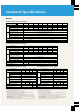
Standard Specifications Ratings ■ Three-Phase 200V Power Supply Model FR-E520- 0.2K 0.4K 0.75K 1.5K 2.2K 3.7K 5.5K 0.1 0.2 0.4 0.75 1.5 2.2 3.7 5.5 7.5 0.3 0.6 1.2 2.0 3.2 4.4 7.0 9.5 13.1 0.8 (0.8) 1.5 (1.4) 3 (2.5) 5 (4.1) 8 (7) 11 (10) 17.5 (16.5) 24 (23) 33 (31) 9 12 17 4.4 (9.7) 4.9 (10.8) Power rated capacity (kVA) (Note 2) Rated current (A) (Note 6) Output Overload current rating (Note 3) 150% for 60 seconds, 200% for 0.
Standard Specifications ■ Common Specifications Control method selection Soft-PWM control or high carrier frequency PWM control; select V/F control or general-purpose flux vector control. Output frequency range Frequency control resolution 0.
External Dimension Diagrams and Terminal Layouts ■ Three-Phase, 200V Power Supply (Frequency Setting Volume Type) ● FR-E520-1.5K, 2.2K The frequency setting knob can be removed. 2-ø5 (0.20) hole The frequency setting knob can be removed. D1 118 (4.65) 128 (5.04) D1 5 (0.20) 5 (0.20) 118 (4.65) 129 (5.08) ø5 (0.20) hole 5 (0.20) 5 (0.20) ● FR-E520-0.1K–0.75K Unit: mm (inch) 5 (0.20) 56 (2.20) 68 (2.68) 11 (0.43) 6 (0.24) 5 (0.20) 68 (2.68) 96 (3.78) 108 (4.25) D2 11 (0.43) 6 (0.
External Dimension Diagrams and Terminal Layouts ■ Three-Phase, 200V Power Supply (CC-Link) ● FR-E520-1.5KN, 2.2KN ø5 (0.20) hole 5 (0.20) 5 (0.20 ● FR-E520-0.1KN, 0.2KN, 0.4KN, 0.75KN Unit: mm (inch) 6 (0.24) 5 (0.20) 56 (2.20) 66 (2.60) 6 (0.24) 128 (5.04) 118 (4.65) 5 (0.20) 128 (5.04) 5 (0.20) 118 (4.65) 2-ø5 (0.20) hole 8 (0.31) 5 30.6 (1.20) 55 (2.17) D D1 4 (0.16) 6 (0.24) 29 (1.14) 68 (2.68) 96 (3.78) 108 (4.25) 30.6 55 (2.17) 65 (2.56) (1.20) 150.6 (5.93) 11 (0.43) 6 (0.
Terminal Connection Diagram ● Frequency Setting Volume Type Inverter FREQROL-E520S, E510W NFB MC R (L2) Single-phase AC power supply S (L2) Inverter FREQROL-E520, E540 NFB MC R (L1) 3-phase AC power supply Motor U S (L2) V T (L3) W IM Short bar P1 PC External transistor common Control input signal STR N (-) High speed RH A Medium speed RM Reverse run start B (Note 4) Brake resistor (optional) Brake unit (optional) High power factor converter FR-HC (option) Error output (Relay o
Description of Terminal Specifications Model type Terminal symbol Main circuit Connected to the commercial power supply. When using a DC power input for units with 3-phase power input specifications, please connect it across terminals R (L1) and S (L2). When using a high power factor converter (FR-HC), do not connect anything. U, V, W Inverter output Connects the 3-phase squirrel cage motor.
Operation ■ Control Panel (Frequency Setting Volume Type) With Cover Open Up/Down keys STOP/RESET key Frequency setting knob Used while running Reverse key Hinged cover (removable) STOP/RESET key RUN key Forward key • 4-digit LED for monitor • Run mode indicator • Operating status Setting key Monitor area MODE key ■ Key Operations ■ Operation 1. Using the Control Panel Knob Use the RUN key to start and the STOP/RESET key to stop. Set the operating frequency with the frequency setting knob.
List of Parameters Series name Function Pr. No.
List of Parameters Series name Function Communications functions PID control Indication Supplementary function Current detection Auxiliary function Supplementary function Manufacturers parameter Initial monitor User functions Terminal function selection Multi-speed operations Auxiliary functions Standard operation function Auxiliary function Stop selection functions Calibration functions Function selection Pr. No.
Description of Parameters Pr. 0–Pr. 6 Note: “Parameter” is sometimes abbreviated “Pr.” Pr. 0 Setting Torque Boost ● The motor torque can be adjusted at low frequencies to match the load. Pr. 4 – 6 Pr. 24 –27 Pr. 232 –239 Setting Multi-Speeds Pr. 4 Three-speed setting (high speed) Pr. 5 Three-speed setting (middle speed) Pr. 6 Three-speed setting (low speed) Output voltage 100% Pr. 24 Multi-speed setting (speed 4) Pr. 25 Multi-speed setting (speed 5) Pr.
Description of Parameters Pr. 7–Pr.14 Pr. 8 Setting Acceleration/ Deceleration Time Pr. 7 Acceleration time frequency Pr. 8 Deceleration time Output frequency Pr. 7 Pr. 10 Operating frequency Time Pr. 12 DC brake voltage Pr. 20 Acceleration/deceleration reference Operating voltage Time Pr. 21 Acceleration/deceleration time increments Pr. 11 Operating time ● Pr. 7 (acceleration time) is the time required from reach the reference frequency of Pr.20 from 0Hz; Pr.
Description of Parameters Pr.15 – Pr. 30 Pr.15 Pr. 16 JOG Operation Settings Pr. 24 Pr. 25 Pr. 26 Pr. 27 See the description of Pr. 4 Pr. 15 JOG frequency Pr. 16 JOG acceleration/deceleration time Pr. 29 ● JOG operation can be run from the control panel. (See manual for details.) ● JOG operation is not available during external operation. Output frequency (Hz) Pr. 20 Pr. 15 JOG frequency setting range Forward Time Reverse Pr. 16 Forward ON Time Reverse Pr.
Description of Parameters Pr. 31–Pr. 43 Pr. 39 Frequency at 20mA Input ● To bypass the resonant frequency of a piece of machinery, jump over that frequency. You can set three jump points. The jump frequency can be the frequency either above or below the jump point. ● The setting for 1A, 2A, or 3A becomes the jump point; operation is at this frequency. Jump (bypass operation) range Output frequency (Hz) Pr. 38 Pr. 35 Pr. 34 Pr. 33 Pr. 32 Pr. 31 3B 3A frequency used for 20mA. Pr.
Description of Parameters Pr. 44 –Pr. 65 Pr. 44 – 48 Setting the 2nd Control Functions Pr. 52 0 Pr. 44 2nd acceleration/deceleration time Output frequency Pr. 45 2nd deceleration time Pr. 47 2nd base frequency Pr. 46 2nd torque boost Pr. 48 2nd electronic thermal O/L relay ● You can change settings such as the acceleration/deceleration time and boost all at once using external contact signals (between terminals RT and SD).
Description of Parameters ● Pr.57 (Coasting Time) Pr. 57 setting Restarting possible 9999 (default) No 0 or 0.1– 5 (Note) Pr.60 setting Function set Description of operation Parameter automatically set 0 (default) Normal operating mode – – Yes The coasting time is the time spent waiting for control to start, which is used for restarting after recovery. Note: When Pr. 57 is set to 0, the standard coasting time described below is set.
Description of Parameters Pr. 66 –Pr.77 Pr. 74 Input Filter Time Constant Pr.66 See the description of Pr. 22 ● You can set the built-in input filter constant of the frequency Pr.70 See the description of Pr. 30 setting signal for the external voltage or current. This aids in removing noise from the frequency setting circuit. ● When noise prevents stable operation, increase the filter time constant. Increasing the setting will lower responsiveness. Pr.
Description of Parameters Pr. 78 –Pr. 96 Pr. 78 Reverse Rotation Prevention Selection ● Set this parameter to prevent problems caused by reverse rotation caused by mistaken start signal input. Pr. 78 setting you need a large starting torque or sufficient low-speed torque. Set the motor capacity. When using a constant torque motor, set Pr.71 (applied motor selection) to 1 or 13–16 (constant torque motor). Forward or reverse both allowed. (Default.) 1 Reverse disabled. 2 Forward disabled.
Description of Parameters Pr. 117–Pr. 151 Pr. 117–124 RS-485 Communications Operation Pr. 145 Switch Parameter Unit Language ● You can switch the language that the parameter unit uses. This setting is enabled when the optional FR-PU04 unit is used. Pr. 117 Station number Pr. 118 Communication speed Pr.145 setting Pr. 119 Stop bit length/data length Language 0 Japanese (default) 1 English Pr. 120 Parity check presence/absence 2 German Pr.
Description of Parameters Pr. 152 –Pr. 192 Zero Current Detection Signals Pr. 152 Pr. 153 Pr. 180 –183 Input Terminal Function Selection Pr. 152 Zero current detection level Pr. 180 RL terminal function selection Pr. 153 Zero current detection period Pr. 181 RM terminal function selection ● When the output current falls below the level set in Pr.152 (zero current detection level) and the time set in Pr.153 (zero current detection time) elapses, the output terminal goes ON.
Description of Parameters Pr. 232 –Pr. 991 Pr. 232 –239 See the description of Pr. 4 Pr.250 Stop Selection ● This parameter selects the stopping method used when the start signal goes OFF (decelerating stop or coasting stop). Pr.244 Fan ON-OFF Control When Pr.250 is 9999 (decelerating stop when start signal goes OFF): ● Controls the cooling fan.
Description of Parameters ● Monitoring Using Digital Display Meter You can display data digitally using a digital counter by employing the pulse train output of the FM terminal. Output is 1440 pulse/sec. at the full scale value described in the section on Pr. 54. When operating frequency is selected for monitoring, you can set the FM output frequency for this terminal using Pr.55. Pr.
Protective Functions The following protective functions are provided for the protection of the inverter itself (except for the motor's electronic thermal relay), but they may also function when the inverter breaks down. Type (Note 5) Function name Description When the inverter output current exceeds the rated current by more than approximately 200% during acceleration/deceleration or at constant speed, the protective circuit activates, halting inverter output.
Connection Examples ■ Basic Wiring Diagram (Operation by External Signal) ● This is the basic inverter wiring diagram when operating by using Inverter forward and reverse switches, an external potentiometer etc. ● For safety, install a magnetic contactor on the input side. NFB MC R (L1) Power supply Notes: 1. To install the model MRS optional external brake resistor to increase braking power, connect it between terminals PR and P (+). 2. Set Pr.
Connection Examples ■ Automatic Operation Using DC 4 –20mA Current Signals MC1 (Note 1) OCR (Note 3) (Building Air-Conditioners) ● This is a sample circuit for automatic operation when used in ● ● ● ● ● combination with controllers such as temperature control for building air-conditioners. You can switch from inverter operation to commercial power supply operation and vice versa. To switch from commercial power supply operation to inverter operation, first stop the motor.
Peripherals ■ Selecting Peripherals Motor output (kW) 3-phase 400V Singlephase 200V Singlephase 100V No-fuse breaker (NFB) or leakage breaker (NV) Magnetic contactors (MC) Lead (mm2) R, S, T (L1, L2, L3) U, V, W AC supply-coordinating reactor DC supply-coordinating reactor Models NF30 and NV30 5A Models NF30 and NV30 5A S-N11 S-N18 S-N20 2 2 FR-BAL-0.4K 0.2 FR-E520-0.1K(N) FR-E520-0.2K(N) (Note 5) S-N18 S-N20 S-N20 2 2 FR-BAL-0.4K (Note 5) 0.4 FR-E520-0.
Peripherals ■ Low-Voltage Standards (1) General-purpose inverters can be used for low-voltage standards. (2) Caution: When using DIN VDE0160, some specifications and cautions differ from the standard, as described in the table below. Specification Changes and cautions Comments Error output Contactor (30V DC, 0.3A) Ground Securely ground equipment and use single wires for ground terminals. – Magnetic contactor, no-fuse breaker Use products that conform to EN or IEC standards.
Optional Equipment ■ List of Options Name Model Application, specifications etc. FR-E5NC Parameter unit (8 languages) FR-PU04 Parameter unit connector cable FR-CB2 Control panel rear cover and adapter set FR-E5P Mounting attachment for EMC filter FR-E5T Brake resistor MRS and MYS models High frequency brake resistor FR-ABR-(H) FR-E540 series only.
Optional Equipment Name (model) Specifications and construction Unit: mm (inch) Mounting screw 2-øC holes D Mounting fixture FR-E5T for EMC filter H H1 H2 Mounting attachment W2 Note: Don't use screws that are so long they will hit the EMC filter. W1 W EMC filter Supplied mounting screw Attachment model FR-E5T01 FR-E5T02 Inverters FR-E520-2.2K, 3.7K FR-E520-5.5K, 7.5K W 199 (7.83) 222 (8.74) W1 188 (7.40) 195 (7.68) W2 5 (0.20) 6 (0.24) Inverter H H1 H2 149 (5.87) 138 (5.43) 118 (4.
Optional Equipment Name (model) Specifications and construction Unit: mm (inch) ● Brake units are optional equipment that increases regenerative braking power. Use them in combination with discharging resistors. ● Select the brake units that match your braking torque requirements. • Selecting a Brake Unit Motor Voltage Braking (kW) torque 50% 100% 50% 100% 200V 400V • Brake Unit/Discharging resistor Combinations 0.4 0.75 1.5 2.2 3.7 5.5 BU-1500 BU-3700 BU-7.5K BU-1500 BU-3700 BU-7.5K BU-15K ∗ BU-H7.
Optional Equipment Name (model) Specifications and construction Unit: mm (inch) B H Inverter Model F FR-BEL 0.4K P (+) P 0.75K Terminal screw size G P1 C Remove short bar D DC supply-coordinating reactor FR-BEL-(H) B C D E F G H 110 6 25 50 94 1.6 95 M3.5 (4.33) (1.97) (3.70) (0.06) (3.74) (0.24) (0.024) (0.98) 120 53 102 1.6 105 6 25 M4 (4.72) (2.09) (4.02) (0.06) (4.13) (0.24) (0.028) (0.98) 130 65 110 1.6 115 6 M4 (5.12) (2.56) (4.33) (0.06) (4.53) (0.24) (0.028) 130 65 110 1.
Optional Equipment Name (model) Specifications and construction S T 4 (0.16) 42 (1.65) 29 (1.14) FR-BLF 65 (2.56) 33 (1.30) 4.5 (0.18) 130 (5.12) 85 (3.35) 7 (0.28) 2.3 80 (3.15) (0.09) 35 (1.38) 65 (2.56) Unit: mm (inch) Power supply 2- 5 (0.20) Notes: 1. Cannot be connected to inverter's output side. 2. Cut wiring as short as possible and connect with inverter's terminal block 7 (0.28) Unit: mm (inch) 110 (4.33) 95 (3.74) FR-BIF 7 (0.28) 29 (1.14) 44 (1.73) 31.5 (1.
Characteristic Data ■ Rotational Speed/Load Torque Characteristics V/F control 300 300 200 200 Rotation speed ( r/min ) 100 0 30 90 180 300 600 900 1200 1500 Load torque (%) Load torque (%) General-purpose flux vector control (slip compensation selected) 1800 –100 100 Rotation speed (r/min) 0 90 300 900 1500 1800 -100 –200 -200 –300 -300 Note: The data shown is for an inverter combined with a Mitsubishi 0.75kW 4P motor.
Motor Applications Application of Special Motors ■ Motors with Brakes Use a motor with a brake that has an independent power supply for the brake, connect the brake supply to the primary supply of the inverter, use the output stop terminal (MRS) for braking (stopping the motor), and turn the inverter output off. Depending on the type of brake, there may be a clattering noise in the brake lining at low speeds. This is not a malfunction.
Cautions ■ Acceleration and Deceleration Times For Maximum Safety ● In order to use the equipment properly and safely, be sure to ● ● ● ● read the manual before use. Mitsubishi general-purpose inverters are not designed or manufactured to be used in equipment or systems in situations that can affect or endanger human life.
Cautions ■ Installing Thermal Relays ■ Wiring Thickness and Length ● The inverter is provided with a protection function that employs ● When the wiring distance between the inverter and the motor is an electronic thermal relay to protect the motor from overheating. When several motors or multi-polar motors are operated using a single inverter, however, install a heat-activated thermal relay (OCR) between the inverter and the motor(s).
Safety Warning To ensure proper use of the products listed in this catalog, please be sure to read the instruction manual prior to use. L-174-9-C3984-B NA9904 Printed in Japan (BUN) Revised publication, effective Apr. 1999 Superseding publication L-174-8-C3984-A Aug. 1998 Specifications subject to change without notice.