
Specifications


Connection Examples
30
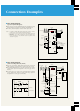
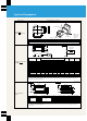
■ Basic Wiring Diagram
(Operation by External Signal)
● This is the basic inverter wiring diagram when operating by using
forward and reverse switches, an external potentiometer etc.
● For safety, install a magnetic contactor on the input side.
Notes: 1. To install the model MRS optional external brake resistor to increase
braking power, connect it between terminals PR and P (+).
2. Set Pr. 54 to be able to select an output current display rather than
frequency.
3. Since Pr. 900 can be used to calibrate the scale of the display meter,
there is no need for a scale calibration resistor except when remote
calibration is required.
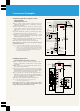
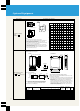
■ Basic Wiring Diagram
(Main Circuit Input Cut-Off by Alarm)
● This is the circuit when cutting off the main inverter circuit input
with a magnetic contactor when an inverter alarm stop occurs.
● The terminal FM-SD output can be either a frequency or a motor
current signal. (See the description of Pr. 54 on page 21 for
details.)
● For reset input, you can also select a function (error reset) that
accepts signals only when the inverter alarm stops. (See the
description of Pr. 75 on page 23 for details.)
IM
R
(
L1
)
MCNFB
Power supply
S
(
L2
)
T
(
L3
)
U
V
W
PR
(+)
P
N
(–)
STF
STR
RES
SD
10(5V)
2
5
A
B
C
FM
SD
E500
LED display
Inverter
Motor
(Note 1)
Forward
Reverse
Reset
Frequency meter
1/2W1kΩ
Error output
(operates during errors)
(Note 3)
Scale calibration
resistor
(Note 3)
Multi-function display
meter output
(1mA full scale)
IM
R
(
L1
)
MC
Power supply
S
(
L2
)
T
(
L3
)
U
V
W
P
P1
NN
HC
HB
HA
STF
(forward when closed)
C
B
STR
(reverse when closed)
RES (Resets when closed)
SD
2
0–5 V/0–10V input
(
input resistance 10kΩ
)
10 (5V)
5
E500
LED display
CR
1
HB HC
F
01X 01Y
Forward start
Reverse start
Reset
Frequency
meter
1/2W1kΩ
Inverter
Motor
Inverter alarm
(opens when alarm occurs)
(inverter trips)
200/100
Tr
Brake unit FR-BU
Resistor
unit
CR
2
MC
Error reset
CR
1
Stop
Preparing
for operation
MC
CR
2
CR
2
MC
R
01X 01Y
Inverter error
Inverter error lamp