
Specifications


42
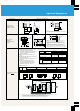
■ Installing Thermal Relays
● The inverter is provided with a protection function that employs
an electronic thermal relay to protect the motor from
overheating. When several motors or multi-polar motors are
operated using a single inverter, however, install a heat-activated
thermal relay (OCR) between the inverter and the motor(s). In
such cases, set the inverter's electronic thermal relay to 0 A and
the OCR setting to 1.0 times the current value on the motor's
rating plate for 50Hz or 1.1 times the value for 60Hz, taking inter-
wire leakage current into account (see page 32 and 33).
■ Eliminating the Capacitor for Enhancing the
Power Factor (Phase-Advance Capacitor)
● The power factor-enhancing capacitor and surge breaker on the
inverter output side may be overheated and damaged by the
harmonic component of inverter output. In addition, an
overcurrent may flow in the inverter and set off the inverter's
overcurrent protection device. Therefore, do not install any
capacitor or surge breaker in the inverters output side. Use a
power-factor-enhancing AC reactor (see pages 36 and 37).
■ Secondary Instrumentation
● When wiring between inverter and motor is long, the effects of
leakage current between lines can generate heat in instruments
and current transformers. Select equipment that has a sufficient
margin in its current rating.
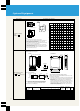
■ Radio Interference
● The input and output of the main inverter circuit contain higher
harmonic components that may interfere with communication
equipment (such as AM radios) and sensors that are being used
close to the inverter. You can reduce interference by attaching a
radio noise filter FR-BIF (for input side only), a line noise filter
FR-BSF01, or an SF type noise filter.
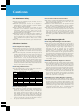
■ Power Supply Harmonics
Harmonics are defined as integer multiples of the base frequency.
Normally, harmonics refers to frequencies up to the 40
th
or 50
th
order of magnitude or greater (up to several kHz). Anything larger
is considered noise. Noise and harmonics are described in the table
below.
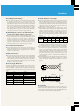
■ Wiring Thickness and Length
● When the wiring distance between the inverter and the motor is
long, the voltage across the main circuit cable drops, especially
for low frequency output. This causes the motor torque to drop.
Use thicker wires between the inverter and the motor so that the
voltage drop is 2% or less. (If wiring is longer than 20m, select
equipment as described on page 32.)
● When wiring is particularly long, the high-response current
limiting function may be engaged by the effects of charge current
caused by floating capacitance in the wiring, so keep the
maximum wiring length within the bounds suggested by the
table below. If you exceed these lengths, change the high-
response current limiting function parameters as described in the
manual.
■ Grounding
The high-speed switching used in these inverters produces more
leakage current than conventional inverters do. Always ground the
inverter and the motor. Furthermore, when grounding the inverter,
it is essential to use the inverter's grounding terminal.
● When operating with general-purpose flux vector control, keep
the wiring length between inverter and motor to 30 m or less. (If
you need more than 30 m of distance, use off-line auto-tuning.)
● To connect the inverter to a parameter unit that is separated from
the inverter, use the special connecting cable, connector adapter,
and rear cover (optional). For remote operation using analog
signals, make sure the control line between the operation box or
operation signal and the inverter is no more than 30 m. Locate
wires away from strong electrical circuits (such as the main
circuit and the relay sequence circuit) to prevent induction from
other equipment.
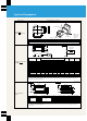
● When setting frequency not with the parameter unit but with an
external potentiometer, use shielded or twisted wire, as shown
below, and connect shielded wire to Terminal 5, not to the
ground.
Item Noise Harmonics
Frequency band Harmonics (10kHz and up)
40th–50th orders (up to several kHz)
Main source Inverter Converter
Transmission route Cable runs, air, induction Cable runs
Effects Distance, wiring routes Line impedance
Quantity produced
Voltage fluctuation rate,
Current capacitance
switching frequency
Physical effect
Malfunctioning sensors, Heat produced by phase-advance
radio noise etc. capacitor, generators etc.
Primary Change wiring routes, install
Install a reactor
countermeasures noise filters
Frequency
setting
equipment
10(10E)
2
5
10(10E)
2
5
Twisted wire
Shielded wire
(1)
(2)
(3)
(1)
(2)
(3)
Frequency
setting
equipment
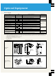
Inverter capacitance 0.1K 0.2K 0.4K 0.75K 1.5K–7.5K
Regular
200m 200m 300m 500m 500m
Maximum
operation
wiring length
Quiet
30m 100m 200m 300m 500m
operation
Cautions